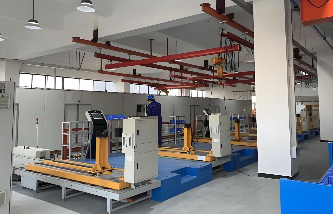
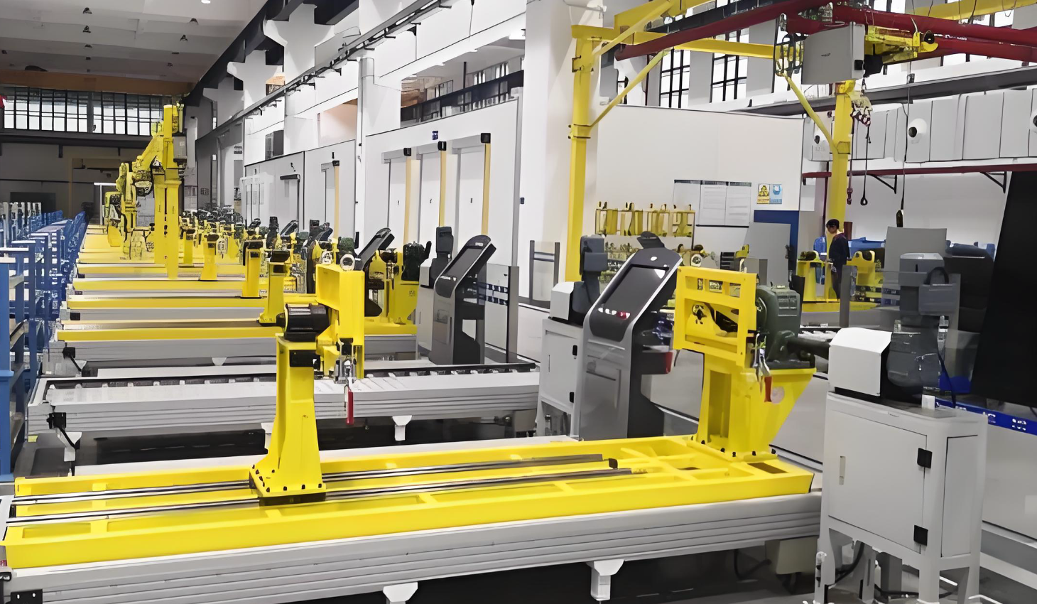
VCB RMU GIS PVB Switchgear Assembly lines / Production lines
- Dry-Type Transformer: Structure, Assembly Process and Automated Production Line
I. Core Structure of Dry-Type Transformer (Three Main Parts + Auxiliary System)
Dry-type transformers operate without insulating oil and rely on natural air cooling. Their core components include the iron core, high and low-voltage windings, insulation system, cooling & temperature control system, enclosure and auxiliary accessories.
1. Iron Core (Magnetic Circuit Core)
- Material: Cold-Rolled Grain-Oriented silicon steel sheets (CRGO, 0.23–0.35 mm) with surface insulating coating, featuring low core loss and high magnetic permeability.
- Structure: Composed of core limbs (for winding installation) and upper/lower yokes (closed magnetic circuit). The mainstream design adopts 45° full miter lap joints and 5–7 stepped lamination, with a lamination stacking coefficient ≥ 0.96, which reduces no-load loss, noise and magnetic reluctance.
- Fastening: Fixed by upper and lower clamping frames and tension straps to ensure tight lamination and minimize vibration.
2. High & Low-Voltage Windings (Circuit Core)
Windings are concentrically sleeved on core limbs with low-voltage windings inside and high-voltage windings outside, optimizing insulation distance and reducing magnetic leakage.
- Low-voltage winding: Foil-wound structure with copper foil is widely used for large-capacity models. Equipped with DMD insulating paper and air channel support strips for excellent heat dissipation, uniform current distribution and strong short-circuit resistance.
- High-voltage winding: Made of flat copper wire or transposed conductor with multi-layer cylindrical or continuous winding structure. Inter-layer and section insulation plus tapping leads ensure reliable insulation and voltage regulation performance.
3. Insulation System (Oil-Free Solid Insulation)
Two mainstream technical solutions:
- Epoxy resin cast type (SCB series): Vacuum casting and pressure integral curing. The coil is fully encapsulated, featuring fire resistance, moisture proof, dust proof and high short-circuit withstand capability, with F/H temperature resistance class.
- Vacuum Pressure Impregnated (VPI): Windings are impregnated with insulating varnish and dried & cured. Cost-effective with superior heat dissipation, suitable for medium/low voltage and small-capacity products.
Insulation materials: DMD insulating paper, Nomex paper, epoxy resin, glass fiber, insulating cylinders and spacing blocks.
4. Cooling & Temperature Control System
- Cooling mode: AN (Natural Air Cooling), AF (Forced Air Cooling with axial fans, increasing rated capacity by 40%). Reserved air ducts between windings to enhance convection heat dissipation.
- Temperature monitoring: PT100 temperature sensors embedded in windings, matched with temperature controllers for over-temperature alarm, trip protection and automatic fan start-stop.
5. Enclosure & Accessories
Protective enclosure (IP20/IP30/IP54), on-load/off-load tap changer, insulators, connecting leads, grounding devices and base frame.
II. Core Assembly Process of Dry-Type Transformer
1. Iron Core Manufacturing Process
- Silicon steel sheet uncoiling → CNC transverse cutting line (high-precision shearing, dimensional tolerance ±0.05mm, burr-free).
- Automatic lamination: stepping lamination, stepped joint design, robot or semi-automatic stacking platform to ensure accurate alignment and tight joint clearance.
- Clamping, shaping and testing: lamination thickness, verticality and insulation resistance inspection before final assembly.
2. Winding Manufacturing Process (Key Procedure)
(1) Low-voltage Foil Winding
Fully automatic foil winding machine: copper foil uncoiling and leveling, constant tension control, alternating lamination of copper foil and DMD insulation paper, air channel strip installation, lead welding and integral shaping.
(2) High-voltage Wire Winding
CNC winding machine: flat wire with constant tension control, precise wire arrangement, inter-layer insulation laying, tapping welding, turn count monitoring and dimensional inspection.
(3) Insulation Curing (Casting / VPI)
- Vacuum casting: Coil mould loading → vacuum degassing → automatic proportioning, mixing and vacuum injection of A/B epoxy resin components → pressure infiltration → rotary heating curing → demoulding and trimming.
- VPI impregnation: Winding loading → vacuum varnish impregnation → pressure treatment → high-temperature drying and curing for uniform insulation penetration.
3. Main Unit Assembly
- Vertical installation and fixing of iron core, concentric sleeving of high and low-voltage windings with uniform coaxial clearance.
- Installation of insulation spacers, air ducts, clamping frames and fasteners with standard torque fastening to prevent loosening and noise.
- Lead welding, tap changer installation, insulation wrapping, grounding connection and overall shaping.
4. Final Assembly & Factory Testing
- Installation of enclosure, cooling fans, temperature controllers, insulators, nameplates and terminal blocks.
- Full electrical performance tests: transformation ratio, DC resistance, insulation resistance, power frequency withstand voltage, induced withstand voltage, partial discharge, no-load & load loss, temperature rise and short-circuit withstand test. Qualified products are allowed for delivery.
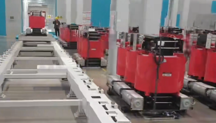
III. Automated Production Line for Dry-Type Transformers
1. Overall Production Line Layout
Divided into 5 integrated modules: iron core automatic line, winding automatic line, main assembly line, intelligent testing line and logistics & MES management system, realizing full-process digital and low-labor production from raw materials to finished products.
2. Core Automatic Equipment & Workstations
(1) Automatic Iron Core Production Line
CNC silicon steel transverse cutting line, robotic automatic lamination workstation, vision positioning system, automatic clamping and flipping equipment, intelligent vertical assembly platform.
(2) Automatic Winding Production Line
Fully automatic CNC foil winding & wire winding machine, servo constant tension system, online dimensional & electrical inspection unit, automatic vacuum casting cell, intelligent VPI impregnation & drying line.
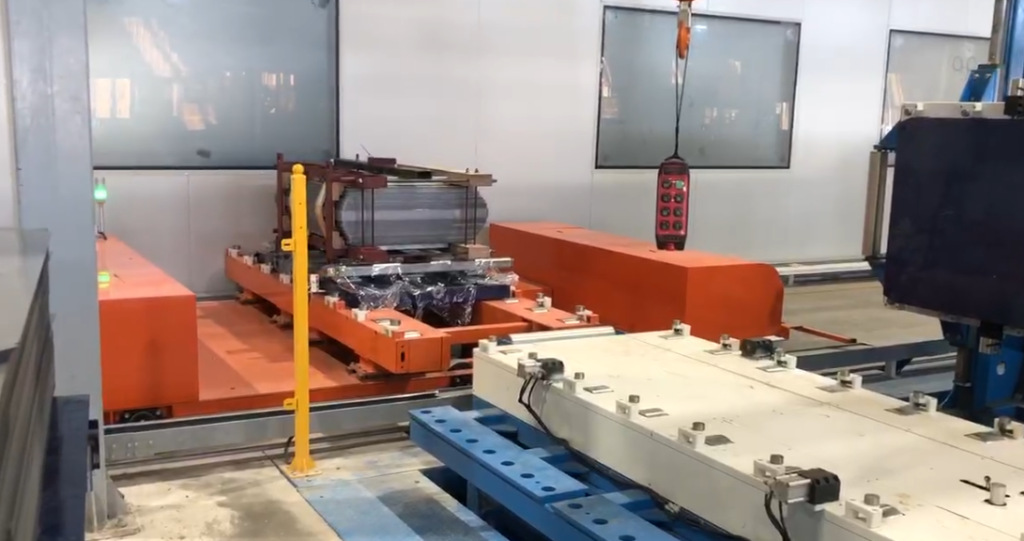
(3) Automated Assembly & Logistics
Robot assembly workstation (automatic winding hoisting, fastener locking and lead welding), AGV intelligent material handling system, speed chain conveyor assembly line, error-proof tooling and full-cycle barcode traceability.
(4) Intelligent Quality Inspection System
Automatic comprehensive test bench for electrical performance, visual appearance inspection, real-time data acquisition, digital twin monitoring and MES/PLM collaborative management, realizing automatic judgment, data archiving and defective product isolation.
3. Advantages of Automated Production Lines
- Efficiency: 30%–50% higher production capacity, shorter delivery cycle and over 50% labor reduction.
- Quality: Stable product consistency, optimized control of loss, noise and partial discharge, and lower defective rate.
- Digitalization: Full-process traceability, flexible model changeover, intelligent scheduling and remote equipment operation & maintenance.
IV. Key Process Control Points
- Iron core: Strict control over lamination accuracy, joint clearance and clamping force to reduce no-load loss and operating noise.
- Winding: Stable winding tension, uniform wire arrangement, standardized insulation thickness and welding quality to ensure insulation reliability and short-circuit resistance.
- Casting process: Accurate vacuum degree, resin ratio, temperature and pressure curing curve to avoid internal bubbles and insulation cracking.
- General assembly: Guaranteed coaxiality, uniform gap, standard fastening torque and lead insulation for optimal electrical and mechanical stability.
- Why a shielded enclosure is required for partial discharge testing of ring main units
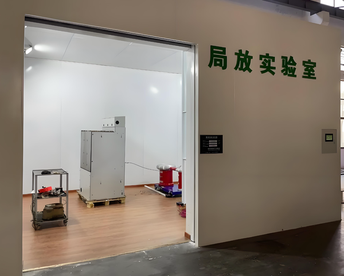
The reason why partial discharge (PD) testing of ring-main units (RMUs) must be carried out inside a shielded room (Faraday cage) is that PD signals are extremely weak (pico-coulomb level, pC), while the on-site electromagnetic environment is complex and the background interference is much higher than the real signal. Without shielding, the test data will be completely “drowned” in noise, making it impossible to identify defects, let alone perform quantitative evaluation. The details can be understood from the following three aspects:
I. Interference sources that the shielded room must “block”
Interference source Typical amplitude Coupling path Influence on PD testing Spatial electromagnetic waves Several mV–tens of mV/m Radiation Directly superimposed on sensor circuit, raising baseline Power-conducted disturbances Tens of mV–several V Power lines Enter HV circuit via coupling capacitance, create “false discharge” Inverter motors, cranes, welders in workshop Wide-band pulses Radiation + conduction Pulse characteristics similar to PD, extremely high false-call rate Lighting, electronic ballasts of air-conditioners Harmonics 10 kHz–1 MHz Radiation Can raise background by 4–6 pC, exceeding pass threshold In an open environment the above interferences easily lift the background to >10 pC, whereas the factory test limit for RMUs is usually ≤5 pC (new unit) or ≤10 pC (in-service unit); the signal is totally submerged and the test becomes meaningless.
II. How the shielded room achieves “low background”
The shielded room is a six-sided continuously welded metal Faraday cage. Combined with filtering and isolation, it can attenuate external interference by 60–120 dB (million–billion times), keeping the indoor background noise <1 pC so that the real PD signal can “surface”. Key technical measures are as follows:
- Electromagnetic shielding
1 mm galvanized steel plates continuously welded on all six sides; doors/windows use knife-edge + beryllium-copper finger strips; shielding effectiveness ≥80 dB at 10 kHz–1 GHz.
- Power isolation & filtering
Mains first pass through a double-shielded isolation transformer and low-pass filter, giving ≥120 dB attenuation for 10 kHz–1 MHz disturbances; indoor lighting and air-conditioner are fed separately to prevent “self-pollution”. - Fully shielded signal cables
All low-voltage signal leads use double-shielded RF coax (triax); connectors are 360° crimped, outer sheath single-point bonded to the cage to break ground loops. - No PD-generating components inside
Lamps are incandescent or DC-powered LEDs; electronic ballasts are forbidden; HV leads are polished and rounded, grading covers and epoxy supports are pre-screened to ensure no “background discharge” from any metal part. - Insulated floor
An 8 mm PPO insulating plate is placed between the shielded-room floor and the building floor, insulation resistance ≥1000 MΩ, blocking common-mode interference coupled through the station earth grid.
III. Consequences of no shielding – data become unreliable
Test scene Measured background Possible outcome Open workshop 20–200 pC Qualified units judged “over-limit”, massive false scrap Ordinary switchgear room 10–50 pC Unable to distinguish “internal defect” from “ambient interference” Inside shielded room <1 pC Real PD of 2–3 pC can be detected, location error ≤10 cm Therefore, the shielded room is not “icing on the cake” but a “hard requirement” for RMU PD testing—without it the stringent requirement of GB/T 7354 and DL/T 417 that “background noise shall be <50 % of the permissible discharge magnitude" cannot be met.
Conclusion
An RMU PD test needs a shielded room because:
- PD signals are weak (pC level) while industrial interference is strong (mV–V level), a difference of >10⁶ times;
- The shielded room reduces the background to <1 pC by "metal cage + power filter + signal shield + single-point earthing", allowing the real defect signal to "surface";
- Only in such a low-noise environment can quantitative measurement and accurate location be performed in accordance with the standards, avoiding false calls and missed calls, and ensuring the traceability and validity of test data.
- Why SF6 RMUs Must Undergo Gas-Tightness Testing and the Methods Used
Gas-tightness tests on SF₆ ring-main units are mandatory because leakage erodes dielectric strength, risks explosion and releases the world’s most potent greenhouse gas. A 0.5 % annual limit safeguards grids, complies with F-Gas/Kyoto rules and preserves carbon credits worth ~1 900 $ per avoided kilogram. Factory helium mass-spectrometry (10⁻¹¹ Pa·m³/s) guarantees zero defects; field pressure-decay or IR laser imaging spots micro-leaks down to 0.5 g/year. On-line density sensors give 24/7 data, enabling predictive seal replacement and cutting lifetime emissions below 3 %.
The following is a full-life-cycle guide to gas-tightness management of SF₆-insulated ring-main units (RMUs). It covers six dimensions: regulations, theory, failure modes, test technologies, on-site implementation and data management. Use it as a pocket handbook.
- Regulations and standards – why 0.5 %/year is a hard limit
1.1 Environmental law
- Kyoto Protocol: SF₆ GWP = 23 500. EU F-Gas Reg. (EU) 517/2014 requires an 80 % cut in emissions by 2030.
- China MEE “Guidelines for SF₆ emission accounting & reporting” (2022): any user storing ≥1 t SF₆ must report annual leakage to the provincial authority. 1 t ≈ 550 RMUs (1.8 kg each); most city utilities easily exceed the threshold.
1.2 Electrical safety
- GB/T 11022-2020 5.103.2: maximum relative annual leakage rate ≤0.5 %.
- GB/T 3906-2020 6.104: type test must include “sealing test”; routine test record must be kept 10 years.
- DL/T 593-2021 allows contractual limit <0.1 % if buyer & supplier agree.
1.3 Carbon trading
- China CCER methodology (2025) accepts SF₆ emission reduction. 1 kg SF₆ saved = 23.5 t CO₂-e. At 80 ¥/t the credit = 1 880 ¥ – “leakage is cash outflow”.
- Physics / chemistry of SF₆ leakage & failure modes
2.1 Sealing principle
- Primary: EPDM O-ring 18–22 % compression, 120 N/mm line pressure at 0.6 MPa (g) fills flange knife marks.
- Secondary: 0.3 mm raised land in groove acts as stop-ridge, prevents O-ring extrusion.
- Tertiary: stainless bellows or TIG weld = “zero-leak barrier”, 25-year maintenance-free in theory.
2.2 Failure contribution (11 utility bursts 2020-2024)
- O-ring ageing 42 % (compression set >30 % after 8 y).
- Casting pores 23 % (0.2 mm pore = 1×10⁻⁵ Pa·m³/s).
- Switching vibration 15 % (30 g shock, bolt preload −8 %/y).
- Thermal cycling stress 12 % (ΔT 60 K, Al vs. SS Δα = 11×10⁻⁶ K⁻¹, shear 80 MPa).
- Others 8 %.
2.3 Leakage curve
- 0–100 h “rapid drop” 2–5 %/y – seating & burr cutting.
- 100 h–7 y “stable permeation” 0.1–0.3 %/y, Fick’s law J = D·ΔC/δ.
- >7 y “accelerated” >0.5 %/y – exponential, seals must be replaced.
- Quantitative test techniques
A. Helium mass-spectrometry (lab)
- Limit: 1×10⁻¹¹ Pa·m³/s ≈ 0.002 g SF₆/y.
- Procedure: vacuum chamber <5 Pa → fill 0.5 MPa He → magnetic-sector analyser.
- Note: SF₆/He conversion factor 1.8; reclaim He or waste 50 L ≈ 120 US$.
B. Pressure-decay (factory / commissioning)
- Fill dry air 0.45 MPa → 24 h rest → ΔP ≤200 Pa.
- Formula: L = ΔP·V·M/(R·T·t·P₀)·365.
Example: 0.14 m³ tank, ΔP = 180 Pa, T = 293 K → L = 0.18 %/y <0.5 % PASS. - Temperature correction: 1 °C = 340 Pa; test at 20 °C ±2 °C or apply α = 1/273 K.
C. Vacuum-decay (sub-assembly)
- Pump to 133 Pa, valve-off 4 h, ΔP ≤25 Pa finds >1×10⁻⁵ Pa·m³/s gross leaks.
D. IR laser imaging (live patrol)
- SF₆ absorbs 10.55 µm; QCL laser creates “black-smoke” image.
- 3 ppm·m ≈ 0.5 g/y; 0–30 m distance, wind <3 m/s; cost ≈ 120 k€.
E. Ultrasound / acoustic camera
- 40 kHz turbulence noise; 128 MEMS microphones, ±2 cm location.
F. On-line density sensor + IoT
- Digital temperature-compensated gauge (−40–+85 °C, ±0.1 %FS) uploads P, T, ρ; algorithm outputs “equivalent annual leakage rate” – SMS alarm at 0.1 % level.
- On-site workflow (10 kV common-tank RMU)
4.1 Acceptance
a) Visual: flange gap, bursting disc, pressure gauge seat, service valve.
b) Bag + quantitative: wrap PVC 30 min, GF306 meter <10 ppm PASS.
c) Pressure-decay: use “night-reading” (22:00 vs 06:00) to cancel diurnal ΔT.
4.2 Patrol (yearly)
- IR + acoustic, two persons, 15 min/RMU; >0.5 g/y = Class-III defect, re-check within 1 month.
4.3 Maintenance policy
- Class I (>5 %/y): immediate outage, return to factory.
- Class II (1–5 %/y): outage within 6 months, replace seals.
- Class III (0.5–1 %/y): planned outage, top-up + on-line monitor.
- Class IV (<0.5 %/y): normal cycle.
- Data management & carbon asset accounting
5.1 Create “birth certificate”: serial No., chamber volume, initial fill, every test date/leakage, top-up history.
5.2 Auto CO₂-e conversion:
Annual leakage (kg) = Initial charge × annual rate
CO₂-e (t) = leakage (kg) × 23.5
Example: 1.8 kg × 0.3 % × 23.5 = 0.127 t CO₂-e/y.
5.3 Upload to provincial MRV platform for CCER claim or green-power trading.
- Design → process → operation leakage-reduction chain
6.1 Design
- Seal groove to ISO 6149-2, Ra ≤0.8 µm.
- Double O-ring + stop-ridge; outer UV-resistant, inner SF₆-low-permeation.
- Bursting disc changed to laser-welded Ni foil, zero gasket.
6.2 Manufacturing
- 100 % He leak after shell welding; enter assembly only if pass.
- IP68 test: 1 m water, 48 h, no bubbles.
- O-ring 200 % compression 70 h; reject if set >15 %.
6.3 Operation
- IR at 1 week & 1 month after energising to catch “infant leakage”.
- Replace disc & gauge every 5 years (edge stress-corrosion is main cause of >7 y bursts).
- Pilot alternative gases: C₄F₇N/CO₂ or dry air, GWP down 98 %, no regulatory risk if leak.
- One-sentence takeaway for management
“Keeping RMU annual SF₆ leakage below 0.5 % is not only a mandatory limit but also a tradable carbon asset; move helium leak testing to the factory, bring IR imaging to field crews, and plug on-line density gauges into IoT, and you can hold lifetime leakage under 3 % – saving ~400 kg CO₂-e per unit, worth about 3 200 ¥ in carbon revenue, enough to pay for all the testing hardware.”
Detailed Summary Table – SF₆ Gas-Tightness Management for Ring Main Units (Life-Cycle View)
No. Dimension Sub-item Key Index / Requirement Applicable Standard / Regulation Stage Recommended Method Cost & Benefit Remarks 1 Regulatory limit Environment GWP = 23 500; EU F-Gas –80 % by 2030 (EU) 517/2014; Kyoto Protocol Design / Operation Carbon accounting 1 kg SF₆ = 23.5 t CO₂-e ≈ 1 900 USD credit China MEE rule ≥1 t must report annually 2 Electrical safety Max. 0.5 % yr⁻¹ leakage GB/T 11022-2020 5.103.2 Type / Routine / Commissioning Helium / pressure decay No type-test certificate if fail Contract may set <0.1 % 3 Carbon trading SF₆ offset accepted in China CCER from 2025 National ETS expansion Operation On-line monitoring + MRV platform 400 kg CO₂-e saved ≈ 3 200 CNY (80 CNY/t) MRV = measurable, reportable, verifiable 4 Failure mode O-ring ageing Compression set >30 % after 8 y StateGrid statistics 42 % 7–10 y IR + ultrasound Replace seals earlier Use low-set EPDM 5 Casting pores 0.2 mm pore → 1×10⁻⁵ Pa·m³/s GB/T 3906-2020 6.104 Pre-delivery Helium 10⁻¹¹ Pa·m³/s Single point fail 100 % welded shell He tested 6 Thermal cycling ΔT 60 K, Al-SS Δα = 11×10⁻⁶ K⁻¹, shear 80 MPa Thermal stress analysis Design Stop-ridge + double O-ring Reduces micro-slip Outdoor units mandatory thermal test 7 Test tech. Helium spectrometer 1×10⁻¹¹ Pa·m³/s ≈ 0.002 g SF₆ yr⁻¹ ISO 15823-2009 Type / Routine Vacuum chamber + magnetic sector Plant 200k USD, 50 L He ≈ 120 USD/unit SF₆/He conversion 1.8 8 Pressure decay 0.45 MPa dry air, 24 h ΔP ≤200 Pa GB/T 3906-2020 Annex C Site acceptance Digital manometer Zero consumable; temp. coeff. 340 Pa/°C Night-reading cancels diurnal drift 9 IR laser imaging 10.55 µm absorption, 3 ppm·m ≈ 0.5 g yr⁻¹ IEC 62485-3 Live inspection QCL laser camera 120k USD set, 0–30 m range Wind <3 m/s; cross-check with ultrasound 10 On-line density sensor ±0.1 %FS, −40–+85 °C DL/T 593-2021 Service IoT upload P,T,ρ 300 USD/node, 10 y life Auto-computes equivalent annual rate 11 Maintenance Defect classes I >5 % yr⁻¹: immediate outage; II 1–5 %: 6 m seal change; III 0.5–1 %: plan top-up; IV <0.5 %: normal StateGrid code Operation Data-driven 60 % fewer forced outages Linked to ERP work orders 12 Design opt. Sealing structure Double O-ring + stop-ridge, groove Ra ≤0.8 µm ISO 6149-2 Design 3D + FEA Life 7→25 y Laser-weld Ni disc = zero gasket 13 Alternative gases C₄F₇N/CO₂ or dry air, GWP −98 % IEC 62271-4 New units Re-calc insulation Same frame needs +0.1 MPa Not for −40 °C yet 14 Economics 25 y leakage Traditional ≈12 % → 5.1 t CO₂-e; Tight <3 % → 1.3 t Carbon 80 CNY/t Whole life Strict control Save 3.2 t×80 = 256 CNY covers 200 CNY test cost Plus green-power premium upside - Regulations and standards – why 0.5 %/year is a hard limit
- The role of power-frequency withstand voltage test in the production of ring main units
Power-frequency withstand-voltage testing is a vital checkpoint in ring-main-unit production. By applying 50 Hz over-voltage—typically 42 kV for 10 kV gear—for one minute, it verifies that insulation between live parts and earth, and across open contacts, can survive service surges without breakdown or flashover. The test reveals hidden defects such as cracks, moisture, or poor assembly, preventing faulty units from reaching the grid. Conducted with a regulated transformer set, gradual voltage rise, and precise leakage-current monitoring, the procedure satisfies GB/IEC standards and forms a mandatory routine test, ensuring every delivered RMU is electrically robust and safe for long-term operation.
Power-frequency withstand voltage testing plays a critical role in the production of ring main units (RMUs). Its core purpose is to verify insulation strength, detect latent defects, and guarantee operational safety. A detailed explanation is given below.
1. The role of power-frequency withstand voltage testing in RMU production
- Verifying that insulation performance meets requirements
As high-voltage distribution apparatus, RMUs must provide adequate insulation between live parts and earth. By applying a voltage several times higher than the rated value, the test simulates possible over-voltages in service and checks whether the insulation is reliable. - Revealing manufacturing defects or hidden weaknesses
The test can expose problems such as ageing, moisture ingress, cracks, contamination of insulating materials, or poor assembly, preventing defective products from being put into operation. - Complying with national standards and industry codes
Power-frequency withstand voltage testing is a mandatory routine test for RMUs before delivery. It satisfies relevant GB, DL, IEC and other standards and constitutes an important criterion for product qualification.
2. Principle of power-frequency withstand voltage testing
The basic principle is:
A power-frequency (50 Hz) high-voltage source impresses the specified high voltage on the insulation of the equipment under test for a set duration (usually 1 min), while observing whether breakdown or flash-over occurs.
Key points of the mechanism:
- Simulating over-voltage conditions: The applied voltage is typically 2–4 times the rated voltage, reproducing extreme situations such as lightning or switching surges.
- Detecting insulation weaknesses: Under high stress, weak spots (e.g., voids, cracks) may break down or exhibit abnormal leakage current, thus being detected.
- Gradual voltage rise: Voltage is increased slowly from zero to avoid damaging sound insulation with sudden shocks and to facilitate observation of any anomaly.
3. Test method and procedure (RMU example)
3.1 Test-set composition
- Power-frequency testing transformer (generates high voltage)
- Regulator (adjusts output voltage)
- Voltmeter & ammeter (monitor voltage and leakage current)
- Protective resistor & voltage divider (protect equipment and personnel)
- Control system (performs voltage ramp, timing, alarm functions)
3.2 Test sequence (example for 10 kV RMU)
Item Test voltage Duration Pass criterion Phase-to-earth & between phases 42 kV 1 min No breakdown, no flash-over, leakage current within limit Across open contacts 48 kV 1 min Same as above - Preparation: Inspect enclosure, terminals, and insulators; set up safety zone; wear insulating PPE.
- Insulation-resistance check: Measure with a megohm meter; confirm >1000 MΩ.
- Voltage application: Raise voltage gradually to the target value, hold for 1 min, watch for breakdown, flash-over, or sudden current change.
- Voltage reduction & recording: After the test, reduce voltage quickly, record data and judge pass/fail.
4. Summary
Power-frequency withstand voltage testing is a key step in RMU production. It ensures insulation safety, uncovers potential defects, and fulfils standard requirements by simulating over-voltage conditions and gradually stressing the insulation, thereby securing the reliability and safety of the equipment in service.
- Verifying that insulation performance meets requirements
- The significance of a dust-free workshop for the assembly of ring main units
Assembling ring-main units inside a dust-tight cleanroom is the only way to keep their gas insulation reliable for 30 years. Even sub-millimetre particles settle on seals or epoxy spacers, create conductive paths, trigger partial discharges and finally cause leakage or explosion. By holding ≥0.5 µm particles below 350 000 m⁻³, humidity under 60 % RH and exposure time of open tanks under 15 min, the cleanroom eliminates these faults at source, guarantees helium leak-rates ≤10⁻⁹ Pa·m³ s⁻¹ and removes the need for on-site maintenance.
Ring-Main Unit (RMU) Assembly Cleanroom: Practical “Zero-Dust” Checklist
If every item below is measured, recorded, and traced, the gas-insulated compartment will stay clean, dry, and tight for 30 years without field maintenance.
- Air Cleanliness – Make dust invisible
1.1 Particle count
– General assembly area: ≤ 350 000 particles ≥ 0.5 µm per m³ (ordinary office ≈ 3 000 000).
– Local laminar zone (seal installation & tank closing): ≤ 35 000 particles ≥ 0.5 µm per m³.
1.2 Air-change rate
– Whole room ≥ 15 ACH; laminar hood 0.3 m/s vertical flow, so dust is swept away before it settles.
1.3 Differential pressure
– +5 Pa vs corridor, +3 Pa between dirty and clean corridors; air moves only one way. - Moisture Control – Keep surface dew-point low
2.1 RH 45 %–55 %, temperature 20 °C ± 2 °C all year; dew-point ≤ 10 °C.
2.2 Every tank is baked at 40 °C for 4 h before assembly; after bake-to-lid time ≤ 30 min to prevent re-absorption. - Parts Cleaning – Remove oil, chips, fingerprints first
3.1 Process: deburr → ultrasonic clean (60 °C neutral detergent, 5 min) → DI-water rinse → hot-air dry (80 °C, 30 min) → double vacuum bag.
3.2 On-site wipe test: white lint-free cloth 10 cm² must show no visible stain; fail = re-wash. - Personnel – Treat humans as the largest contaminator
4.1 Entry sequence: tacky mat ×2 → gown → hood → coverall → booties → roller → air-shower 20 s.
4.2 Self-roller every 2 h; end-of-shift tacky-mat weight gain ≤ 5 mg/cm², else retraining.
4.3 No pens, paper, cosmetics; only cleanroom paper & pen allowed. - Tools & Logistics – Stop re-contamination
5.1 Dedicated stainless trolleys; wheels cleaned on tacky mat daily.
5.2 Trays: 2 mm anti-static UPE, Ra ≤ 0.8 µm, zero particle release.
5.3 Torque wrenches, sockets ultrasonically cleaned weekly and stored in sealed boxes after use. - Real-Time Monitoring – Replace “feeling” with figures
6.1 Laser particle counter every 4 h; record 0.3 µm & 0.5 µm; stop line if limit exceeded.
6.2 Dew-point probe continuous; alarm at –5 °C, stop lid work, start extra dryers.
6.3 “Black-cloth inspection” under 1 000 lx LED: 30 s visual check before closing; any visible speck blown off with ionized air gun. - Open-Time Budget – Expose guts as briefly as possible
7.1 Tank open → wipe → install seal → close lid within 15 min; else re-evacuate and back-fill dry air.
7.2 O-ring out-of-bag to groove ≤ 5 min. - Vacuum & Leak Test – Kill leakage before dispatch
8.1 Immediate evacuation to ≤ 100 Pa, hold 2 h; pressure rise ≤ 50 Pa/h.
8.2 Back-fill 0.05 MPa dry N₂ (dew-point –60 °C), helium sniff ≤ 1×10⁻⁹ Pa·m³/s (≈ 1 g loss in 30 years). - Daily Cleanroom Up-keep – Make cleanliness a habit
9.1 HEPA/ULPA filters changed every 6 months or when ΔP reaches 2× initial.
9.2 Floor & wall: lint-free mop + DI water daily; IPA wipe weekly.
9.3 “Dust map”: 1 m × 1 m grid, 10 % sampled monthly; white-glove wipe greyscale ≤ grade 1 (no visible stain vs new glove).
Follow the nine sections quantitatively and traceably, and the RMU will operate for three decades without dust tracking, partial discharge, or gas leakage.
- Air Cleanliness – Make dust invisible
- What are the testing devices in the power switchgear production line?
In the production line of power switchgear, various testing devices are utilized to ensure the quality and safety of the products. These include power frequency withstand voltage testers for insulation verification, circuit resistance testers for checking conductive paths, insulation resistance testers for secondary circuits, relay protection testers for control functions, mechanical characteristic testers for breaker performance, comprehensive testing platforms for multiple assessments, partial discharge testing platforms for insulation integrity, RCD testers for safety compliance, and power-on test benches for functional checks. These devices collectively ensure that switchgear meets high standards before deployment.
The following are common testing devices used in the production line of power switchgear, along with detailed explanations:
Primary Circuit Testing Equipment
- Power Frequency Withstand Voltage Testing Equipment: Used to perform AC withstand voltage tests on the primary circuit of switchgear to inspect its insulation performance. This ensures that the switchgear can withstand a certain level of voltage without insulation breakdown during normal operation and overvoltage conditions. During the test, voltage is applied to the primary circuit according to specified values and duration, and any discharge phenomena are observed.
- Circuit Resistance Tester: A circuit resistance tester with a current of no less than 100A is used to measure the contact resistance and conductive resistance of primary equipment such as circuit breakers in the closed state. This helps to judge the conductive performance of the equipment and identify any poor contact issues, thereby ensuring the normal transmission of current.
Secondary Circuit Testing Equipment
- Insulation Resistance Tester: An insulation resistance tester with a voltage of 500V is used to measure the insulation resistance of the auxiliary and control circuits of switchgear. By measuring the insulation resistance value, the insulation condition of the secondary circuit can be judged, preventing short circuits or leakage faults caused by insulation aging or moisture, and ensuring the safe and reliable operation of the secondary circuit.
- Relay Protection Tester: Different voltage levels are applied to the operating mechanism to verify whether it can operate normally. This ensures that the control and protection functions of the switchgear can be accurately executed under different voltage conditions, guaranteeing the safe and stable operation of the power system.
Mechanical Characteristic Testing Equipment
- Switchgear Mechanical Characteristic Tester: Used to measure parameters such as closing time, opening time, and opening/closing synchronicity of circuit breakers. These parameters are crucial for ensuring the reliable opening and closing operations of circuit breakers. Accurate measurement and analysis can determine whether the mechanical performance of the circuit breaker meets the requirements, and identify and address any potential mechanical faults in a timely manner, ensuring its rapid and accurate operation in the power system.
Comprehensive Testing Equipment
- Switchgear Comprehensive Testing Platform: Integrated with various AC and DC power sources, this platform can meet multiple testing requirements simultaneously, significantly improving work efficiency. The input power is three-phase four-wire AC 380V, and it can output power with different voltages and currents, used for comprehensive detection of switchgear, including power-on tests, operating voltage tests, closing power tests, etc.
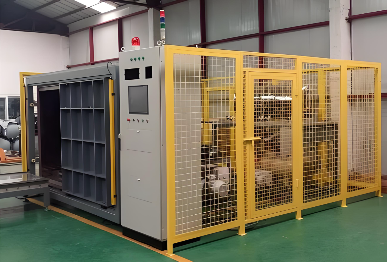
Special Testing Equipment
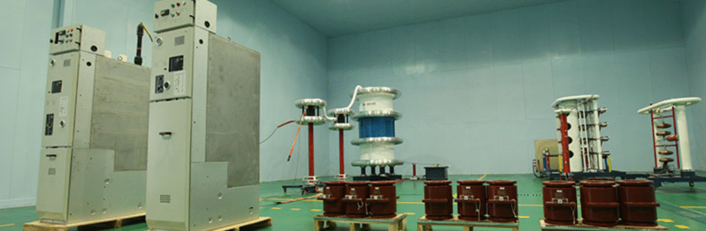
- Partial Discharge Testing Platform: Comprising a double-shielded isolation transformer, a fully shielded room, line filters, high-voltage filters, and a partial discharge tester, this platform can effectively suppress interference from power networks and spatial electromagnetic waves. It accurately detects partial discharge conditions inside switchgear, allowing for the early identification of potential insulation defects and preventing equipment failures and power outages caused by partial discharges.
Other Testing Equipment
- Residual Current Device (RCD) Tester: Used to test parameters such as the residual current tripping value, tripping time, and non-tripping current of RCDs. This ensures that RCDs can reliably cut off the power supply in case of leakage, safeguarding personnel and equipment.
- Power-On Test Bench: Provides a simulated actual operating environment for switchgear, allowing for power-on tests to check whether the functions of the switchgear are normal under power-on conditions, such as indicator light display, switch operation, and the absence of abnormal heating or noise.
The following table lists the testing devices used in the power switchgear production line:
Equipment Name Main Function Scope of Application Power Frequency Withstand Voltage Testing Equipment AC withstand voltage test for primary circuit 12KV/24KV/40.5KV Solid Sealed High Voltage Switchgear, etc. Circuit Resistance Tester Measure the contact resistance and conductive resistance of primary equipment 12KV Gas Insulated High Voltage Switchgear, etc. Insulation Resistance Tester Measure the insulation resistance of auxiliary and control circuits Secondary circuits of various switchgear Relay Protection Tester Verify the operation of the operating mechanism Control and protection functions of various switchgear Switchgear Mechanical Characteristic Tester Measure closing time, opening time, etc. of circuit breakers Circuit breakers of various switchgear Switchgear Comprehensive Testing Platform Integrated with various power sources for multiple detections Comprehensive detection of various switchgear Partial Discharge Testing Platform Detect partial discharge inside switchgear Insulation detection of various switchgear Residual Current Device (RCD) Tester Test parameters of RCDs Residual current devices in switchgear Power-On Test Bench Perform power-on tests to check functions Power-on detection of various switchgear 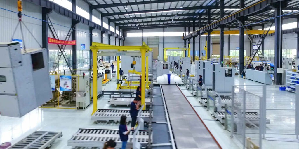
During the testing process of power switchgear, the following protective measures need to be taken:
Electrical Safety Protection
- Insulation Protection: Operators should wear insulating gloves, insulating shoes, and other insulating protective equipment to avoid direct contact with live parts and prevent electric shock accidents.
- Grounding Protection: Ensure that the testing equipment and the switchgear being tested are reliably grounded. The grounding wire should be securely connected, and the grounding resistance should meet the requirements to prevent leakage and static electricity accumulation.
- Voltage Level Marking: Clearly mark the voltage level and danger warning signs in the testing area to remind personnel of the high voltage danger and prevent accidental entry into live areas.
- Isolation Measures: Use safety barriers or isolation screens to separate the testing area from non-testing areas, and set up clear warning signs to prevent unauthorized personnel from entering the testing area.
Personal Protection
- Safety Helmets: All personnel entering the testing site must wear safety helmets to protect against accidental head impacts.
- Protective Eyewear: When performing operations that may produce arcs, sparks, or splashes, such as withstand voltage testing or mechanical characteristic testing, operators should wear protective eyewear to protect their eyes from injury.
- Earplugs or Earmuffs: In high-noise environments, such as during switch operations or mechanical testing, earplugs or earmuffs should be worn to protect hearing from damage.
Equipment Protection
- Overload Protection: Testing equipment should be equipped with overload protection devices that automatically cut off the power supply when the current or voltage exceeds the rated value of the equipment, protecting it from damage.
- Moisture and Dust Protection: Ensure that the storage environment for testing equipment and switchgear is dry and clean to prevent the effects of moisture and dust on the insulation and mechanical performance of the equipment.
- Equipment Securing: When performing mechanical characteristic tests or vibration tests, the equipment being tested should be securely fastened to prevent it from shifting or toppling during the test, which could cause equipment damage or personal injury.
Environmental Protection
- Good Ventilation: The testing site should have good ventilation to prevent the accumulation of harmful gases or smoke, especially during withstand voltage testing or partial discharge testing when gases may be generated that need to be promptly expelled.
- Fire Prevention Measures: The testing site should be equipped with fire extinguishers and other fire-fighting equipment to ensure that fires can be promptly extinguished. At the same time, avoid storing flammable materials in the testing area.
Emergency Measures
- First Aid Equipment: The testing site should be equipped with a first aid kit containing commonly used first aid medicines and equipment to allow for initial treatment in case of personnel injury.
- Emergency Exit Routes: Ensure that there are clear emergency exit routes at the testing site and keep them unobstructed to allow personnel to evacuate quickly in case of emergency.
- Emergency Plan: Develop a detailed emergency plan that clearly defines the procedures and responsibilities for handling emergencies such as electric shock, fire, and equipment failure. Regularly organize emergency drills to improve personnel’s emergency response capabilities.
- Intelligent Production System for Switchgear Cabinet Sheet Metal Processing with Robots
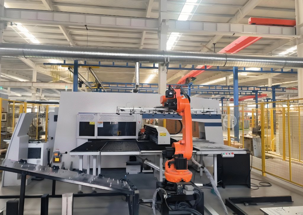
I. Equipment Composition
1. Storage Unit
- Function: Mainly used for the storage of raw materials, semi-finished products, and finished products. It connects with the cutting and shearing unit, bending unit, and palletizing unit to achieve the input and output of materials.
- Composition:
- Racking: Used for storing raw materials and finished products of different specifications. The racking is designed reasonably to meet the storage needs of materials of various sizes and weights.
- Stacker Crane: Responsible for transporting materials between the racks to achieve automated storage and retrieval. The stacker crane is equipped with an advanced navigation system that can accurately locate the position of the racks to ensure the precise transportation of materials.
- Conveyor System: Connects the storage unit with various processing units to transport materials from the storage unit to the processing units, or from the processing units back to the storage unit. The conveyor system uses belt or roller conveyors, which are characterized by stable operation and low noise.
- Features:
- Automated Storage and Retrieval: Through an automated control system, it realizes the automated storage and retrieval of materials, improving storage efficiency.
- Inventory Management: Equipped with an advanced inventory management system that monitors the inventory of materials in real-time, facilitating the formulation of production plans and the replenishment of materials.
- Flexible Design: The racking and conveyor system can be adjusted flexibly according to production needs to adapt to the storage of materials of different specifications and quantities.
2. Cutting and Shearing Unit
- Function: Performs cutting and shearing operations on raw materials. The processed components can be directly sent to the bending unit or returned to the storage unit as needed.
- Composition:
- Press Brake: Used for punching and blanking operations on raw materials. The press brake is equipped with a high-precision numerical control system that can achieve complex punching patterns and high-precision processing requirements.
- Shearing Machine: Used for shearing operations on raw materials. The shearing machine is equipped with an automatic feeding device that can achieve continuous shearing, improving production efficiency.
- Robot Loading and Unloading System: The robot is responsible for transporting raw materials from the storage unit to the cutting and shearing unit and sending the processed components to the bending unit or back to the storage unit. The robot is equipped with an advanced vision system that can accurately identify and grasp materials.
- Features:
- High-Precision Processing: The press brake and shearing machine are equipped with high-precision numerical control systems to ensure the dimensional and positional accuracy of the processed components.
- Automated Loading and Unloading: The robot loading and unloading system achieves automated operation, reducing manual intervention and improving production efficiency and processing quality.
- Flexible Processing: The cutting and shearing unit can quickly adjust processing parameters to adapt to the processing needs of raw materials of different specifications and shapes.
3. Bending Unit
- Function: Composed of bending robots and bending machines, it can achieve automatic centering, bending, flipping, and palletizing processes for side panels and front panels of switchgear cabinets, realizing unmanned operations.
- Composition:
- Bending Robot: Responsible for transporting the processed components from the cutting and shearing unit to the bending machine and assisting in the bending process. The bending robot is designed with advanced articulated joints, offering high flexibility and precision.
- Bending Machine: Used for bending operations on components. The bending machine is equipped with a high-precision numerical control system and an automatic centering device, capable of achieving complex bending processes and high-precision processing requirements.
- Flipping Device: Used to flip the components to the specified position to facilitate multi-angle bending operations by the bending machine.
- Features:
- High-Precision Bending: The bending machine, with its high-precision numerical control system and automatic centering device, ensures the dimensional and angular accuracy of the bent components.
- Automated Operation: The combination of bending robots and bending machines achieves automated bending, reducing manual intervention and improving production efficiency and processing quality.
- Flexible Processing: The bending unit can quickly adjust bending parameters to adapt to the processing needs of components of different specifications and shapes.
4. Palletizing Unit
- Function: Used to stack the finished products for convenient transportation and storage.
- Composition:
- Palletizing Robot: Responsible for transporting the finished products from the bending unit to the palletizing area and stacking them neatly according to the specified palletizing method. The palletizing robot is designed with advanced articulated joints, offering high flexibility and precision.
- Palletizing Platform: Used for storing the stacked finished products. The palletizing platform is designed reasonably to meet the stacking needs of finished products of different specifications and quantities.
- Conveyor System: Connects the palletizing unit with the storage unit to transport the stacked finished products to the storage unit for storage.
- Features:
- Automated Palletizing: The palletizing robot achieves automated palletizing, improving palletizing efficiency and quality.
- Flexible Palletizing: The palletizing robot can adjust the palletizing method flexibly according to the specifications and quantities of the finished products, adapting to different palletizing needs.
- Safety and Reliability: The palletizing platform and conveyor system are designed reasonably to ensure the safety and reliability of the palletizing and transportation processes.
5. Data Management and Control Unit
- Function: The core of data management and control for the entire system, responsible for the transmission, collection, processing, and output of control commands to achieve intelligent management and control of the entire production process.
- Composition:
- Central Control System: In charge of controlling and managing the entire production system, including monitoring the operating status of equipment, formulating and scheduling production plans, collecting and analyzing data, etc.
- Network Communication System: Enables data communication between various equipment to ensure the rapid transmission and sharing of information.
- Data Acquisition System: Responsible for collecting operating data from various equipment and quality data from the production process, providing data support for production management and quality control.
- Features:
- Intelligent Management and Control: Through the central control system, it achieves intelligent management and control of the entire production process, improving production efficiency and quality.
- Real-Time Monitoring and Scheduling: Real-time monitoring of the operating status of equipment and production progress, dynamic scheduling according to production plans to ensure the smooth progress of the production process.
- Data Analysis and Optimization: By analyzing production data, it optimizes production processes and equipment parameters to improve production efficiency and quality.
6. Robots and Supporting Equipment
- Function: Composed of multiple articulated robots and supporting feeding platforms, the vision-guided robots equipped with automatic tightening guns complete operations such as riveting and welding.
- Composition:
- Articulated Robots: Used to perform various processing operations, such as riveting and welding. The articulated robots are designed with advanced articulated joints, offering high flexibility and precision.
- Feeding Platform: Used to supply materials needed for processing by robots. The feeding platform is designed reasonably to meet the supply needs of materials of different specifications and quantities.
- Vision System: Used to guide robots to perform precise operations, such as grasping materials and locating processing positions. The vision system uses advanced image recognition technology to achieve high-precision vision guidance.
- Automatic Tightening Gun: Used to complete operations such as riveting and welding. The automatic tightening gun is equipped with a high-precision torque control system to ensure the quality of riveting and welding.
- Features:
- High-Precision Operation: The combination of articulated robots and vision systems achieves high-precision operations, improving processing quality.
- Automated Processing: Robots and supporting equipment achieve automated processing, reducing manual intervention and improving production efficiency and processing quality.
- Flexible Processing: Robots and supporting equipment can quickly adjust processing parameters to adapt to the processing needs of materials of different specifications and shapes.
II. Process Features
1. High Degree of Automation
- Description: It adopts a streamlined production process of automatic loading, cutting, shearing, bending, and palletizing, replacing the traditional single-machine operation mode in separate areas. This reduces manual intervention and improves production efficiency and product quality.
- Advantage: Reduces manual operation, lowers labor intensity, and enhances production efficiency and processing quality.
2. Flexible Production
- Description: It can quickly adapt to the processing needs of switchgear cabinet sheet metal parts of different specifications and models, with fast production changes and short preparation times. It has high adaptability and versatility, enabling the production of multiple varieties and small batches.
- Advantage: Quickly responds to market demands, improves production flexibility and market competitiveness.
3. High Processing Precision
- Description: By using high-precision robots and numerical control equipment, as well as advanced vision systems and other technologies, it ensures the dimensional and positional accuracy of the processed components, improving the stability of product quality.
- Advantage: Improves product quality, reduces the rate of defective products, and enhances the corporate brand image.
4. High Production Efficiency
- Description: Robots can process continuously without interruption, significantly improving production efficiency. Compared with traditional processing methods, the processing efficiency of a complete set of sheet metal parts can be increased by more than 40%.
- Advantage: Improves production efficiency, shortens production cycles, and meets market demands.
5. Reliable Quality
- Description: Robots operate in a standardized and stable manner, avoiding quality fluctuations caused by human factors, ensuring better finished product quality.
- Advantage: Improves the stability of product quality, reduces quality complaints, and lowers after-sales costs.
6. Energy-Saving and Environmental Protection
- Description: The entire production process is more efficient and energy-saving, reducing energy consumption and waste generation, in line with the requirements of sustainable development.
- Advantage: Reduces production costs, minimizes environmental pollution, and complies with environmental protection policies.
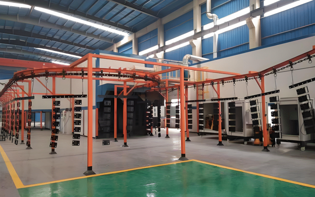
- Options for Switchgear Cabinet Sheet Metal Painting Surface Coatings Production Line
Characteristics of Surface Coatings on Power Switchgear Enclosures
- Good Adhesion: The coating firmly adheres to the surface of the enclosure, ensuring long-term protection even when subjected to mechanical impacts or vibrations.
- Excellent Wear Resistance: In the usage of switchgear, the coating withstands frequent friction and wear, such as during switch operations and equipment handling, extending its service life and maintaining its protective and decorative functions.
- Strong Corrosion Resistance: Power switchgear is often exposed to various complex environments, where it may come into contact with corrosive media like moisture and chemicals. The surface coating provides strong corrosion resistance, preventing rust and corrosion of the enclosure, ensuring its normal operation and extending its lifespan.
- Aesthetic Appearance: The coating has a uniform color and smooth surface, enhancing the overall aesthetic quality of the switchgear, making it more visually appealing and in line with modern industrial equipment standards.
- Good Insulation Properties: For power switchgear, insulation is crucial. The coating offers additional insulation protection, reducing the risk of electrical leakage due to surface coating damage and enhancing the safety of the switchgear.
Surface Treatment Process for Power Switchgear Enclosures
- Pre-treatment:
- Degreasing: Using degreasing agents to remove oils and grease from the enclosure surface, providing a clean surface for subsequent treatment processes. Common degreasing methods include chemical degreasing and electrochemical degreasing.
- Pickling: Removing scale, rust, and other impurities from the enclosure surface through pickling, revealing the fresh metal substrate and creating a suitable surface for coating adhesion. After pickling, neutralization is required to remove residual acid.
- Phosphating: Forming a uniform phosphate layer on the enclosure surface, which enhances the adhesion between the coating and the metal substrate and improves the corrosion resistance of the coating. There are various phosphating processes, such as zinc phosphate and iron phosphate.
- Spraying:
- Electrostatic Spraying: A widely used spraying process in modern industry. It utilizes an electrostatic field to attract charged paint particles to the grounded workpiece surface, forming a uniform coating. Electrostatic spraying offers advantages such as uniform coating, strong adhesion, high paint utilization, and minimal environmental pollution, making it suitable for large-scale industrial production.
- Arc Spraying: A thermal spraying technique that heats the coating material to a molten state using an electric arc and sprays it onto the workpiece surface using compressed air to form a coating. Arc spraying can produce coatings with high bond strength, good wear resistance, and corrosion resistance, suitable for applications with high coating performance requirements.
- Curing: The sprayed coating needs to undergo curing treatment to allow the resin and other components in the coating to undergo chemical reactions, forming a hard protective film. Curing methods include natural drying, hot air drying, and infrared curing. Among these, hot air drying and infrared curing can accelerate the curing process and improve production efficiency.
Spray Painting Production Line Equipment
- Pre-treatment Equipment:
- Degreasing Tank: Used for holding degreasing agents to perform degreasing on the enclosure. It typically includes heating and stirring devices to ensure effective degreasing.
- Pickling Tank: Used for the pickling process. The tank is made of acid-resistant materials, such as plastic or stainless steel. It also features heating and stirring devices to ensure uniform distribution and complete reaction of the pickling solution.
- Phosphating Tank: Used for phosphating treatment, with a structure similar to the pickling tank. The temperature and solution concentration in the tank need to be controlled according to the specific phosphating process requirements.
- Spraying Equipment:
- Electrostatic Spraying Equipment: Comprises an electrostatic spray gun, high-voltage electrostatic generator, and powder recovery system. The spray gun is a key component for coating quality; the high-voltage electrostatic generator provides the electrostatic field for the spray gun; the powder recovery system recovers excess powder that did not adhere to the workpiece surface, improving paint utilization.
- Arc Spraying Equipment: Mainly consists of a spraying power supply, wire feeding device, and spray gun. The spraying power supply provides the current and voltage required for the electric arc, the wire feeding device evenly feeds the coating material into the spray gun, and the spray gun sprays the molten material onto the workpiece surface.
- Curing Equipment:
- Baking Oven: The primary device for curing the coating. The uniformity of the internal temperature of the oven is crucial for ensuring coating quality. The heating methods of the baking oven include radiation, hot air circulation, and a combination of radiation and hot air circulation. Depending on the production requirements, the oven can be single-chamber or through-type, and the equipment can be straight-through or bridge-type. Hot air circulation baking ovens offer good insulation, uniform temperature distribution, and low heat loss. Tests have shown that the temperature difference within the oven is less than ±3°C.
- Infrared Curing Equipment: Utilizes the heat from infrared radiation to quickly cure the coating. It has advantages such as fast curing speed, low energy consumption, and compact equipment size, but it has certain requirements for the thickness and material of the coating.
- Conveying Equipment: Used to transport the enclosure workpieces along the production line. Common types include overhead conveyors, ground roller conveyors, and elevators. The conveying equipment needs to be designed according to the layout and process requirements of the production line to ensure smooth transfer of workpieces between different processes.
- Auxiliary Equipment: Also includes devices for detection and control, such as coating thickness gauges, temperature and humidity sensors, and automated control systems. Coating thickness gauges are used to monitor the thickness of the coating to ensure it meets the required specifications. Temperature and humidity sensors help maintain the optimal environmental conditions for the coating process, while automated control systems manage the entire production line, ensuring efficient and consistent operations.
Characteristics and Benefits of Automated Assembly Line Production for Surface Coating of Power Distribution Cabinet Enclosures in the Power Industry
Automated assembly line production for surface coating of power distribution cabinet enclosures in the power industry has the following significant characteristics and numerous benefits:
Characteristics
- High Degree of Automation: The entire coating production process, from loading the workpieces to pre-treatment, spraying, curing, and unloading, is fully automated, requiring minimal manual intervention. This greatly improves production efficiency and the stability of product quality.
- Continuous Production: The assembly line production method allows workpieces to flow continuously between various processes, reducing downtime and waiting times in the production process. It enables large-scale, continuous production, meeting the power industry’s demand for mass production of distribution cabinets.
- Integrated Processes: Multiple surface coating treatment processes, such as degreasing, pickling, phosphating, electrostatic spraying, and curing, are integrated into a single production line. This achieves a compact and integrated process flow, saving production space and improving equipment utilization.
- Precise Control: With advanced automated control systems, various parameters in the production process, such as temperature, humidity, spraying pressure, paint flow rate, and conveying speed, can be precisely controlled. This ensures the consistency and uniformity of coating quality, effectively avoiding quality fluctuations caused by human factors.
Benefits
- Increased Production Efficiency: The automated assembly line can quickly and continuously complete the surface coating of distribution cabinet enclosures, significantly reducing production cycles and increasing output per unit of time. This helps power companies quickly respond to market demands and enhance their market competitiveness.
- Improved Product Quality: Automated equipment ensures that coating thickness, uniformity, adhesion, and other quality indicators reach high levels. This provides better protection, decorative effects, and insulation properties for the surface coating of distribution cabinet enclosures. As a result, the service life of distribution cabinets is extended, and their operational reliability and safety are improved.
- Reduced Labor Costs: The need for manual labor is reduced, lowering labor costs. At the same time, reducing manual operations also decreases the risk of quality issues and safety accidents caused by human errors, further reducing the operational costs of enterprises.
- Optimized Production Environment: Automated assembly line production systems are typically equipped with complete exhaust gas treatment and dust recovery systems. These can effectively reduce the emission of harmful gases and dust during the spraying process, improving the production environment and meeting environmental protection requirements. This is conducive to the sustainable development of enterprises.
- Enhanced Production Flexibility: Although primarily used for mass production, automated assembly line production systems can also meet the production requirements of different specifications and coating types of distribution cabinet enclosures to a certain extent by adjusting process parameters and equipment configurations. This provides a certain degree of production flexibility to adapt to the diverse product needs of the power industry.
- Traceability of Data: Automated control systems can record various data from the production process, such as production time, process parameters, and equipment operating status. This enables traceability of product quality. In the event of quality issues, the problematic link can be quickly located, facilitating cause analysis and quality improvement.
- KYN28 Switchgear – Composition and Manufacturing Process
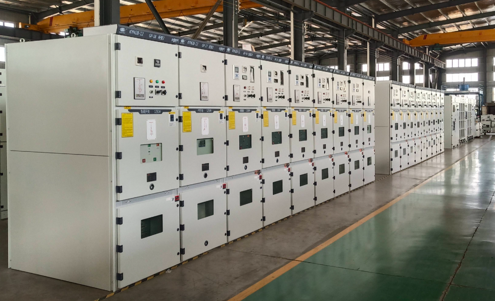
1. Composition of KYN28 Switchgear
KYN28 (also known as KYN28-12 armored withdrawable metal-clad switchgear) is a 10 kV distribution assembly widely used in power systems. It consists of two main parts—the enclosure and the withdrawable truck (draw-out circuit-breaker compartment). Internally it is divided into four independent, fully segregated functional compartments:
Compartment Main Components & Function Instrument Compartment Houses micro-processor relays, meters, indicators, push-buttons, and other secondary devices for monitoring and protection. Circuit-Breaker Compartment (Truck Bay) Contains a withdrawable vacuum circuit-breaker truck (e.g., VS1 or VD4) with three defined positions—service, test, and isolated. Features shutter mechanisms and guide rails. Busbar Compartment Houses three-phase main and branch busbars, fully insulated by sleeves or boots, supporting high-current systems and preventing arc propagation. Cable Compartment Accommodates current transformers, earthing switches, surge arresters, and cable terminations. Spacious enough for up to six single-core cables in parallel. Additional elements include pressure-relief channels and a complete “five-prevention” interlock system (against mis-operation, live switching, energised earthing, etc.).
2. Manufacturing Process of KYN28 Switchgear
Manufacturing is characterised by high modularity, standardisation, and intelligent quality control. Key steps are:
2.1 Enclosure Fabrication
- Material: 2 mm thick Aluzinc or hot-dip-galvanised steel sheet for superior oxidation and corrosion resistance.
- Machining: CNC turret punching and multi-bend forming ensure dimensional accuracy and interchangeability.
- Assembly: High-tensile bolted or riv-nut construction eliminates welding distortion and allows rapid field assembly.
2.2 Surface Protection
- Electrostatic powder coating or epoxy-polyester spray to achieve IP4X protection and long-term corrosion resistance.
2.3 Busbar Processing
- Copper bars are tin-plated or sleeved with heat-shrink insulation; aluminium bars are wrapped with insulating sleeves.
- Insulating boots or covers on joints prevent arc tracking.
- For ratings ≥ 2500 A, busbar chambers include additional epoxy insulators to prevent deformation under short-circuit forces.
2.4 Truck & Interlock System
- Truck movement via a precision lead-screw mechanism for smooth, accurate positioning.
- Mechanical and electrical dual interlocks ensure operator safety and prevent mal-operation.
2.5 Intelligence & Testing
- Optional integration of temperature/humidity sensors, partial-discharge monitors, and intelligent operator interfaces for remote diagnostics.
- Routine tests: power-frequency withstand voltage, mechanical endurance (≥10 000 operations), and interlock-function verification before shipment.
Structural Layout (Schematic)
┌──────────────┐
│ Instrument Compartment (Top)   │ ← Secondary control & protection
├──────────────┤
│ Busbar Compartment (Upper Rear)│ ← Main & branch busbars
├──────────────┤
│ Circuit-Breaker Compartment    │ ← Withdrawable vacuum breaker
├──────────────┤
│ Cable Compartment (Lower)      │ ← Cables, CTs, VTs, arresters
└──────────────┘
KYN28 Switchgear
Assembly & Test Process FlowThe following flow is based on a proven production line with an annual output of 5 000 units. “Assembly” and “Testing” are divided into 14 key stations (S0–S13). Each station lists the main tasks, quality-control points (QC), required records, and tooling/fixtures; the data can be dropped directly into work instructions (WI) or standard operating procedures (SOP).
1 Process Overview
Phase Station Name Purpose Takt Key Record Prep S0 Material kitting & IQC Prevent wrong/mixed parts 30 min Incoming-inspection sheet Build S1 Frame assembly Ensure geometric accuracy 20 min Assembly checklist Build S2 Partition/rail mounting Form separate compartments 15 min Dimension check sheet HV S3 Busbar fabrication & mounting Current-carrying & dynamic stability 25 min Busbar log HV S4 CT & surge-arrester mounting Measuring & over-voltage protection 10 min Torque record LV S5 Secondary harness pre-fab Reduce on-site wiring 30 min Wire list LV S6 Secondary wiring & termination Signal integrity 25 min Continuity test log Mech S7 Truck / breaker insertion Mechanical fit 10 min Truck interchange log Mech S8 Mechanical interlock adjustment “Five-prevention” verification 15 min Interlock test sheet Close S9 Cover & pressure-relief mounting IP & relief path 10 min Visual-inspection sheet Test S10 Power-frequency withstand test 42 kV / 1 min 8 min HV test report Test S11 Relay setting & functional test Secondary-system correctness 20 min Relay sheet Final S12 Final factory acceptance test Full-item FAT 15 min FAT report Ship S13 Packing & dispatch Anti-corrosion, anti-shock 10 min Packing list Total takt ≈ 3.5 h/unit (one 8-hour shift yields 2 units).
2 Detailed Process Steps
S0 Material Kitting & IQC
- Tasks: Scan barcode → verify specs → random visual/dimensional check → affix IQC PASS label.
- QC: Copper bus thickness; tin-plating ≥ 8 µm; insulation parts UL94 V-0.
S1 Frame Assembly
- Tasks:
- Assemble Aluzinc side frames, cross beams and base plate with M8 bolts + riv-nuts;
- Use 3-D right-angle fixture: diagonal error ≤ 1 mm.
- Tooling: Pneumatic torque wrench 25 N·m.
S2 Partition / Rail Mounting
- Tasks: Mount metal partitions, shutter mechanisms, truck rails; conductive paste on grounding lugs—surface must be metal-bright.
- QC: Rail horizontality ≤ 0.5 mm / 1 000 mm.
S3 Busbar Fabrication & Mounting
- Tasks:
- CNC busbar machine performs punching, chamfering and embossing in one pass;
- Heat-shrink tube oven 120 °C / 10 min;
- After mounting, re-torque M12 bolts to 50 N·m.
- QC: Contact resistance ≤ 20 µΩ.
S4 CT & Surge-Arrester Mounting
- Tasks: Remove CT secondary shorting links before installation; arrester ground lead directly to main earth bar.
- Record: CT ratio & polarity measured values.
S5 Secondary Harness Pre-Fabrication
- Tasks: Automatic cut-strip-crimp machine cuts wire → crimps terminals → inserts heat-shrink sleeves → 100 % continuity check.
- QC: Wire diameter tolerance ±0.1 mm; crimp height per JST standard.
S6 Secondary Wiring & Termination
- Tasks:
- Route wires in trunking; bend radius ≥ 6D;
- Terminal screws torque 0.8 N·m;
- Check continuity & insulation > 100 MΩ (DC 500 V).
S7 Truck / Breaker Insertion
- Tasks:
- Apply conductive grease No. 3 on plug-in contacts;
- Two intermediate stops to verify shutter opening/closing synchronism;
- Interchangeability check: insertion force ≤ 300 N for same-type trucks.
S8 Mechanical Interlock Adjustment
- Tasks:
- Manual & electrical open/close 50 cycles, record timing;
- Verify five-prevention functions:
- Earth switch ON → truck cannot be racked-in;
- Breaker closed → door electromagnetic lock cannot be released.
- Tooling: Mechanical-characteristic tester.
S9 Cover & Pressure-Relief Plate Mounting
- Tasks: Fit explosion-proof film inside relief plate; add spring washers to bolts; check IP4X slot gap ≤ 2.5 mm.
S10 Power-Frequency Withstand Test
- Conditions: phase-to-phase & phase-to-earth 42 kV / 1 min; across open contacts 48 kV / 1 min; leakage ≤ 10 mA.
- Safety: 8 mm insulating mat, audible-visual alarm, access interlock.
S11 Relay Setting & Functional Test
- Tasks:
- Inject secondary current with relay test set to verify over-current, instantaneous, earth-fault;
- Simulate undervoltage & anti-pumping circuits;
- Record pick-up, reset ratio, operating time.
S12 Final Factory Acceptance Test (FAT)
- Per GB 3906-2020:
- Visual, mechanical operation, interlocks, insulation, main-circuit resistance, secondary-circuit withstand, instrument indication consistency.
- Issue stamped FAT report.
S13 Packing & Dispatch
- Tasks:
- Vacuum bag + desiccant + anti-shock foam;
- Wooden crate labels “UP”, “MOISTURE PROOF”, “DO NOT INVERT”;
- ERP scan-out, transport tracking number sent to customer.
3 Quality-Control Summary
Item Standard Instrument Frequency Frame diagonal difference ≤ 1 mm Steel tape 100 % Busbar joint resistance ≤ 20 µΩ Loop-resistance tester Each unit Secondary insulation ≥ 100 MΩ 500 V megger 100 % Power-frequency withstand 42 kV / 1 min no flashover HV test set 100 % Mechanical life 10 000 ops no fault Mechanical tester Type test 4 Man-Hours & Manpower (per unit)
- Structure assembly: 2 workers × 60 min
- HV installation: 2 workers × 35 min
- Secondary wiring: 2 workers × 55 min
- Test & commissioning: 2 workers × 43 min
- Packing: 1 worker × 10 min
Total: 9 man-hours/unit (excluding material handling).
- Functions and Manufacturing Technology of Each Compartment in a Ring Main Unit (RMU)
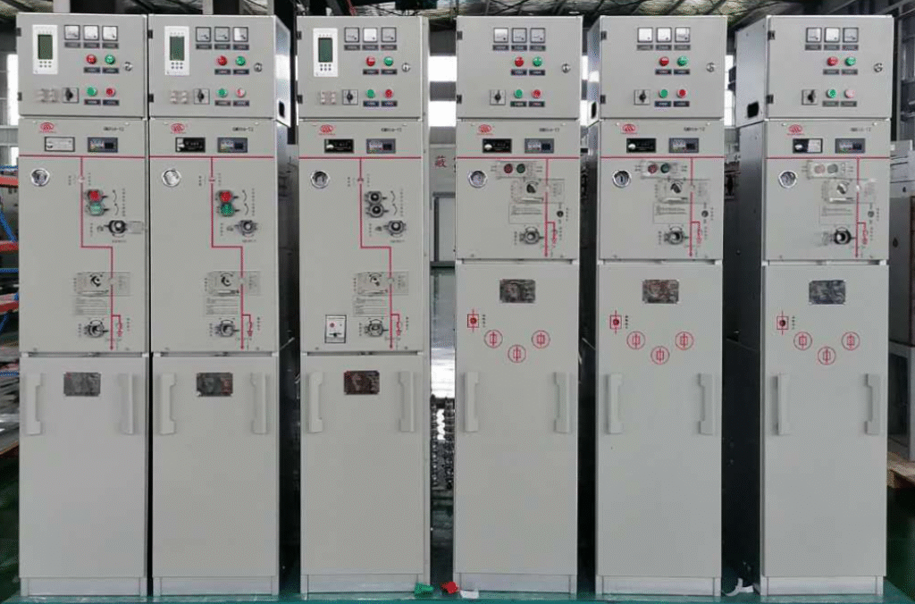
✅ 1. Functional Compartments/Enclosures of a Ring Main Unit (RMU)
Compartment / Enclosure Primary Function Switchgear Compartment Houses load-break switches, circuit breakers and earthing switches for making or breaking current, short-circuit interruption and earthing. Fuse Compartment Accommodates high-voltage current-limiting fuses that, in combination with the load-break switch, protect transformers against overload and short-circuit. Operating-Mechanism Compartment Contains manual or motor-operated spring-charged mechanisms for closing, opening and earthing operations. Cable Compartment (Base Frame) Provides space for cable entry/exit, fixing, earthing, and installation of current/voltage transformers and zero-sequence CTs. Metering & Control Compartment (optional) Installs secondary devices such as protection relays and DTU (Distribution Terminal Unit) to enable “remote measurement, remote signalling and remote control”. Gas Tank / SF₆ Enclosure A sealed tank that encloses the main primary components (three-position switch, busbars), filled with SF₆ or an eco-friendly gas for insulation and arc extinction. ✅ 2. Manufacturing Processes of Ring Main Units (SF₆-insulated type as example)
Stage Description Enclosure Fabrication 3 mm stainless-steel plates are laser-cut and welded, ensuring a leakage rate ≤ 0.01 % per year. Gas-Tank Assembly Load-break switches, busbars and three-position switches are modularised and installed inside the sealed tank, which is then filled with SF₆ or eco-friendly gas. Cable-Compartment Assembly Integrates plug-in type CT/VTs, cable clamps, PT elbows and zero-sequence CTs for reliable connections and easy maintenance. Secondary Wiring Secondary devices (protection relays, DTU) are mounted on the door or in the control compartment, followed by wiring and functional tests. Testing & QA Includes power-frequency withstand tests, partial-discharge tests, gas-tightness checks and lightning-impulse tests. Automated Production Line MES system and automatic helium-leak detection equipment realise full-process automation, traceability and quality control. ✅ 3. Typical Structural Types Comparison – American vs European
Type Features American Common-Tank All circuits in one enclosure, compact footprint, maintenance-free, suitable for outdoor use. European Common-Tank Separate compartments for each functional unit (switchgear, busbar, etc.), modular design, easy extension and maintenance. Individual Gas Tank (Air-insulated or Gas-insulated) Each functional unit has its own sealed tank with SF₆ or eco-gas insulation, ideal for urban networks demanding high reliability. Manufacturing Process of a Ring Main Unit (RMU)
The entire production cycle can be summarized in five main phases: enclosure fabrication → primary assembly → secondary wiring → testing → shipment. Each step is governed by strict workmanship and quality-control checkpoints.
1. Enclosure Fabrication
- Material: 2.5–3 mm non-magnetic stainless steel (SUS 304).
- Cutting & Bending: Laser cutting → CNC bending → robotic welding; welds are 100 % helium-leak tested.
- Surface Treatment: Seven-stage pre-treatment (degreasing → rinsing → phosphating …) → thermal-spray zinc–aluminium alloy → polyurethane powder coating, total thickness ≥ 80 µm for outdoor salt-fog resistance.
- Enclosure Features
– Double-door design: front door for operation & metering, rear door for cable compartment, both with three-point locking.
– Pressure-relief channel: bottom or top vent flaps to direct arc gases safely outward during internal arc faults.
2. Primary Assembly
- Gas-Tank Pre-assembly
– Robotically welded “sealed for life” tank, leakage rate ≤ 0.1 % per year.
– Vacuum evacuated, then back-filled with SF₆ or dry air slightly above atmospheric pressure; 30-year maintenance-free. - Main-circuit Module Installation
– Three-position switch (close–open–earth) + busbars + vacuum circuit breaker / load-break switch pushed into the tank as a complete module. - Cable Compartment Fit-up
– Integrated CTs/VTs, zero-sequence CT, cable clamps, separable PT elbows positioned for zero cable crossing and easy maintenance. - Operating Mechanism Mounting
– Spring-operated mechanism coupled to the three-position switch; manual and motor charging, mechanical position indication and interlocking adjusted simultaneously.
3. Secondary Wiring & Protection System
- Device Installation
– Relays, DTU, auxiliary relays, temperature-humidity controller, compartment lighting mounted on door or dedicated metering cubicle. - Wiring Practice
– Harness routed in cable ducts or corrugated conduits, dual-end ferrules; CT secondary circuits earthed at one point. - Terminals & Labelling
– Screwless spring-type terminals, segregated incoming/outgoing sides; each wire carries both QR code and text labels for full traceability.
4. Testing & Quality Control
Test Item Content / Standard Power-frequency withstand 1.2 Ur for 1 min, no flashover Partial discharge ≤ 5 pC @ 1.1 Ur Gas tightness (helium) ≤ 0.1 % annual leakage Mechanical endurance 3-pos switch ≥ 5 000 operations Secondary injection Verify pickup & timing of overcurrent, earth-fault, differential relays Primary injection 100 % In through primary circuit, verify CT ratio & phase Routine Factory Test (FAT) Witnessed by customer or third party; test certificates & reports issued 5. Final Inspection, Packing & Shipment
- Final Check
– Appearance, labels, keys, spare-parts list; door opening angle ≥ 120°, locks smooth. - Packing
– PE film wrap + fumigated plywood crate + desiccant; shipping marks “moisture-sensitive”, “keep upright”, “fragile”. - Documentation
– Factory test report, certificate of conformity, wiring diagrams (AutoCAD PDF), O&M manual, warranty card.
6. Typical Production-Line Layout (minutes per station)
1 Enclosure loading → 2 Gas-tank welding/leak test → 3 Primary module insertion → 4 Secondary wiring → 5 Complete unit testing → 6 Packing → 7 Warehousing/shipping
MES integration records welding parameters, SF₆ fill data and test curves in real time for full traceability.The above process complies with IEC 62271-200, IEC 62271-103 and GB 3906 requirements and can be fine-tuned for solid-insulated, eco-gas or primary-secondary integrated RMUs.