
Why SF6 RMUs Must Undergo Gas-Tightness Testing and the Methods Used
Gas-tightness tests on SF₆ ring-main units are mandatory because leakage erodes dielectric strength, risks explosion and releases the world’s most potent greenhouse gas. A 0.5 % annual limit safeguards grids, complies with F-Gas/Kyoto rules and preserves carbon credits worth ~1 900 $ per avoided kilogram. Factory helium mass-spectrometry (10⁻¹¹ Pa·m³/s) guarantees zero defects; field pressure-decay or IR laser imaging spots micro-leaks down to 0.5 g/year. On-line density sensors give 24/7 data, enabling predictive seal replacement and cutting lifetime emissions below 3 %.
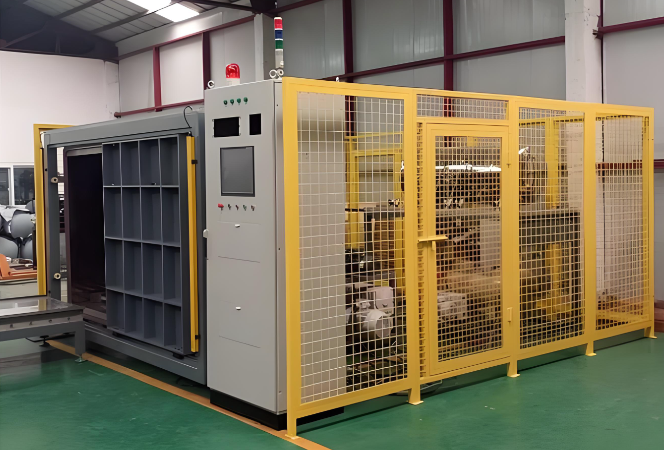
The following is a full-life-cycle guide to gas-tightness management of SF₆-insulated ring-main units (RMUs). It covers six dimensions: regulations, theory, failure modes, test technologies, on-site implementation and data management. Use it as a pocket handbook.
- Regulations and standards – why 0.5 %/year is a hard limit
1.1 Environmental law
- Kyoto Protocol: SF₆ GWP = 23 500. EU F-Gas Reg. (EU) 517/2014 requires an 80 % cut in emissions by 2030.
- China MEE “Guidelines for SF₆ emission accounting & reporting” (2022): any user storing ≥1 t SF₆ must report annual leakage to the provincial authority. 1 t ≈ 550 RMUs (1.8 kg each); most city utilities easily exceed the threshold.
1.2 Electrical safety
- GB/T 11022-2020 5.103.2: maximum relative annual leakage rate ≤0.5 %.
- GB/T 3906-2020 6.104: type test must include “sealing test”; routine test record must be kept 10 years.
- DL/T 593-2021 allows contractual limit <0.1 % if buyer & supplier agree.
1.3 Carbon trading
- China CCER methodology (2025) accepts SF₆ emission reduction. 1 kg SF₆ saved = 23.5 t CO₂-e. At 80 ¥/t the credit = 1 880 ¥ – “leakage is cash outflow”.
- Physics / chemistry of SF₆ leakage & failure modes
2.1 Sealing principle
- Primary: EPDM O-ring 18–22 % compression, 120 N/mm line pressure at 0.6 MPa (g) fills flange knife marks.
- Secondary: 0.3 mm raised land in groove acts as stop-ridge, prevents O-ring extrusion.
- Tertiary: stainless bellows or TIG weld = “zero-leak barrier”, 25-year maintenance-free in theory.
2.2 Failure contribution (11 utility bursts 2020-2024)
- O-ring ageing 42 % (compression set >30 % after 8 y).
- Casting pores 23 % (0.2 mm pore = 1×10⁻⁵ Pa·m³/s).
- Switching vibration 15 % (30 g shock, bolt preload −8 %/y).
- Thermal cycling stress 12 % (ΔT 60 K, Al vs. SS Δα = 11×10⁻⁶ K⁻¹, shear 80 MPa).
- Others 8 %.
2.3 Leakage curve
- 0–100 h “rapid drop” 2–5 %/y – seating & burr cutting.
- 100 h–7 y “stable permeation” 0.1–0.3 %/y, Fick’s law J = D·ΔC/δ.
- >7 y “accelerated” >0.5 %/y – exponential, seals must be replaced.
- Quantitative test techniques
A. Helium mass-spectrometry (lab)
- Limit: 1×10⁻¹¹ Pa·m³/s ≈ 0.002 g SF₆/y.
- Procedure: vacuum chamber <5 Pa → fill 0.5 MPa He → magnetic-sector analyser.
- Note: SF₆/He conversion factor 1.8; reclaim He or waste 50 L ≈ 120 US$.
B. Pressure-decay (factory / commissioning)
- Fill dry air 0.45 MPa → 24 h rest → ΔP ≤200 Pa.
- Formula: L = ΔP·V·M/(R·T·t·P₀)·365.
Example: 0.14 m³ tank, ΔP = 180 Pa, T = 293 K → L = 0.18 %/y <0.5 % PASS. - Temperature correction: 1 °C = 340 Pa; test at 20 °C ±2 °C or apply α = 1/273 K.
C. Vacuum-decay (sub-assembly)
- Pump to 133 Pa, valve-off 4 h, ΔP ≤25 Pa finds >1×10⁻⁵ Pa·m³/s gross leaks.
D. IR laser imaging (live patrol)
- SF₆ absorbs 10.55 µm; QCL laser creates “black-smoke” image.
- 3 ppm·m ≈ 0.5 g/y; 0–30 m distance, wind <3 m/s; cost ≈ 120 k€.
E. Ultrasound / acoustic camera
- 40 kHz turbulence noise; 128 MEMS microphones, ±2 cm location.
F. On-line density sensor + IoT
- Digital temperature-compensated gauge (−40–+85 °C, ±0.1 %FS) uploads P, T, ρ; algorithm outputs “equivalent annual leakage rate” – SMS alarm at 0.1 % level.
- On-site workflow (10 kV common-tank RMU)
4.1 Acceptance
a) Visual: flange gap, bursting disc, pressure gauge seat, service valve.
b) Bag + quantitative: wrap PVC 30 min, GF306 meter <10 ppm PASS.
c) Pressure-decay: use “night-reading” (22:00 vs 06:00) to cancel diurnal ΔT.
4.2 Patrol (yearly)
- IR + acoustic, two persons, 15 min/RMU; >0.5 g/y = Class-III defect, re-check within 1 month.
4.3 Maintenance policy
- Class I (>5 %/y): immediate outage, return to factory.
- Class II (1–5 %/y): outage within 6 months, replace seals.
- Class III (0.5–1 %/y): planned outage, top-up + on-line monitor.
- Class IV (<0.5 %/y): normal cycle.
- Data management & carbon asset accounting
5.1 Create “birth certificate”: serial No., chamber volume, initial fill, every test date/leakage, top-up history.
5.2 Auto CO₂-e conversion:
Annual leakage (kg) = Initial charge × annual rate
CO₂-e (t) = leakage (kg) × 23.5
Example: 1.8 kg × 0.3 % × 23.5 = 0.127 t CO₂-e/y.
5.3 Upload to provincial MRV platform for CCER claim or green-power trading.
- Design → process → operation leakage-reduction chain
6.1 Design
- Seal groove to ISO 6149-2, Ra ≤0.8 µm.
- Double O-ring + stop-ridge; outer UV-resistant, inner SF₆-low-permeation.
- Bursting disc changed to laser-welded Ni foil, zero gasket.
6.2 Manufacturing
- 100 % He leak after shell welding; enter assembly only if pass.
- IP68 test: 1 m water, 48 h, no bubbles.
- O-ring 200 % compression 70 h; reject if set >15 %.
6.3 Operation
- IR at 1 week & 1 month after energising to catch “infant leakage”.
- Replace disc & gauge every 5 years (edge stress-corrosion is main cause of >7 y bursts).
- Pilot alternative gases: C₄F₇N/CO₂ or dry air, GWP down 98 %, no regulatory risk if leak.
- One-sentence takeaway for management
“Keeping RMU annual SF₆ leakage below 0.5 % is not only a mandatory limit but also a tradable carbon asset; move helium leak testing to the factory, bring IR imaging to field crews, and plug on-line density gauges into IoT, and you can hold lifetime leakage under 3 % – saving ~400 kg CO₂-e per unit, worth about 3 200 ¥ in carbon revenue, enough to pay for all the testing hardware.”
Detailed Summary Table – SF₆ Gas-Tightness Management for Ring Main Units (Life-Cycle View)
| No. | Dimension | Sub-item | Key Index / Requirement | Applicable Standard / Regulation | Stage | Recommended Method | Cost & Benefit | Remarks |
|---|---|---|---|---|---|---|---|---|
| 1 | Regulatory limit | Environment | GWP = 23 500; EU F-Gas –80 % by 2030 | (EU) 517/2014; Kyoto Protocol | Design / Operation | Carbon accounting | 1 kg SF₆ = 23.5 t CO₂-e ≈ 1 900 USD credit | China MEE rule ≥1 t must report annually |
| 2 | Electrical safety | Max. 0.5 % yr⁻¹ leakage | GB/T 11022-2020 5.103.2 | Type / Routine / Commissioning | Helium / pressure decay | No type-test certificate if fail | Contract may set <0.1 % | |
| 3 | Carbon trading | SF₆ offset accepted in China CCER from 2025 | National ETS expansion | Operation | On-line monitoring + MRV platform | 400 kg CO₂-e saved ≈ 3 200 CNY (80 CNY/t) | MRV = measurable, reportable, verifiable | |
| 4 | Failure mode | O-ring ageing | Compression set >30 % after 8 y | StateGrid statistics 42 % | 7–10 y | IR + ultrasound | Replace seals earlier | Use low-set EPDM |
| 5 | Casting pores | 0.2 mm pore → 1×10⁻⁵ Pa·m³/s | GB/T 3906-2020 6.104 | Pre-delivery | Helium 10⁻¹¹ Pa·m³/s | Single point fail | 100 % welded shell He tested | |
| 6 | Thermal cycling | ΔT 60 K, Al-SS Δα = 11×10⁻⁶ K⁻¹, shear 80 MPa | Thermal stress analysis | Design | Stop-ridge + double O-ring | Reduces micro-slip | Outdoor units mandatory thermal test | |
| 7 | Test tech. | Helium spectrometer | 1×10⁻¹¹ Pa·m³/s ≈ 0.002 g SF₆ yr⁻¹ | ISO 15823-2009 | Type / Routine | Vacuum chamber + magnetic sector | Plant 200k USD, 50 L He ≈ 120 USD/unit | SF₆/He conversion 1.8 |
| 8 | Pressure decay | 0.45 MPa dry air, 24 h ΔP ≤200 Pa | GB/T 3906-2020 Annex C | Site acceptance | Digital manometer | Zero consumable; temp. coeff. 340 Pa/°C | Night-reading cancels diurnal drift | |
| 9 | IR laser imaging | 10.55 µm absorption, 3 ppm·m ≈ 0.5 g yr⁻¹ | IEC 62485-3 | Live inspection | QCL laser camera | 120k USD set, 0–30 m range | Wind <3 m/s; cross-check with ultrasound | |
| 10 | On-line density sensor | ±0.1 %FS, −40–+85 °C | DL/T 593-2021 | Service | IoT upload P,T,ρ | 300 USD/node, 10 y life | Auto-computes equivalent annual rate | |
| 11 | Maintenance | Defect classes | I >5 % yr⁻¹: immediate outage; II 1–5 %: 6 m seal change; III 0.5–1 %: plan top-up; IV <0.5 %: normal | StateGrid code | Operation | Data-driven | 60 % fewer forced outages | Linked to ERP work orders |
| 12 | Design opt. | Sealing structure | Double O-ring + stop-ridge, groove Ra ≤0.8 µm | ISO 6149-2 | Design | 3D + FEA | Life 7→25 y | Laser-weld Ni disc = zero gasket |
| 13 | Alternative gases | C₄F₇N/CO₂ or dry air, GWP −98 % | IEC 62271-4 | New units | Re-calc insulation | Same frame needs +0.1 MPa | Not for −40 °C yet | |
| 14 | Economics | 25 y leakage | Traditional ≈12 % → 5.1 t CO₂-e; Tight <3 % → 1.3 t | Carbon 80 CNY/t | Whole life | Strict control | Save 3.2 t×80 = 256 CNY covers 200 CNY test cost | Plus green-power premium upside |