KYN28 Switchgear – Composition and Manufacturing Process
1. Composition of KYN28 Switchgear
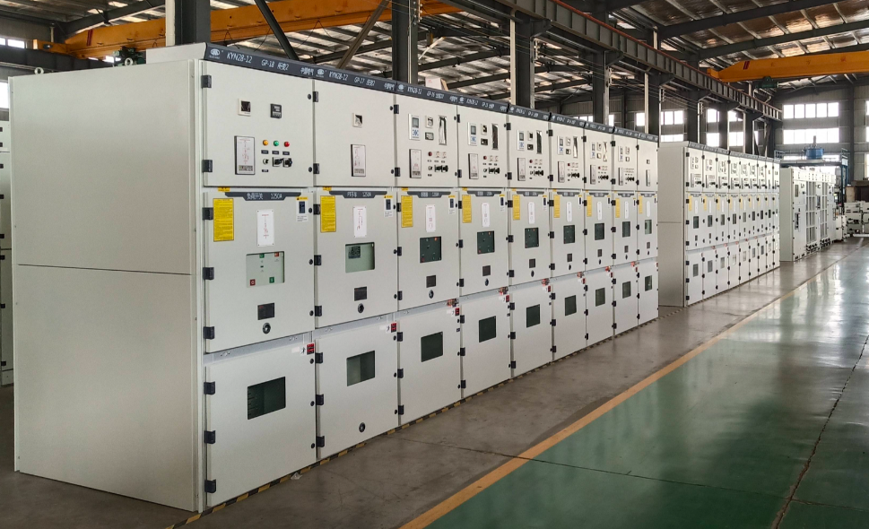
KYN28 (also known as KYN28-12 armored withdrawable metal-clad switchgear) is a 10 kV distribution assembly widely used in power systems. It consists of two main parts—the enclosure and the withdrawable truck (draw-out circuit-breaker compartment). Internally it is divided into four independent, fully segregated functional compartments:
| Compartment | Main Components & Function |
|---|---|
| Instrument Compartment | Houses micro-processor relays, meters, indicators, push-buttons, and other secondary devices for monitoring and protection. |
| Circuit-Breaker Compartment (Truck Bay) | Contains a withdrawable vacuum circuit-breaker truck (e.g., VS1 or VD4) with three defined positions—service, test, and isolated. Features shutter mechanisms and guide rails. |
| Busbar Compartment | Houses three-phase main and branch busbars, fully insulated by sleeves or boots, supporting high-current systems and preventing arc propagation. |
| Cable Compartment | Accommodates current transformers, earthing switches, surge arresters, and cable terminations. Spacious enough for up to six single-core cables in parallel. |
Additional elements include pressure-relief channels and a complete “five-prevention” interlock system (against mis-operation, live switching, energised earthing, etc.).
2. Manufacturing Process of KYN28 Switchgear
Manufacturing is characterised by high modularity, standardisation, and intelligent quality control. Key steps are:
2.1 Enclosure Fabrication
- Material: 2 mm thick Aluzinc or hot-dip-galvanised steel sheet for superior oxidation and corrosion resistance.
- Machining: CNC turret punching and multi-bend forming ensure dimensional accuracy and interchangeability.
- Assembly: High-tensile bolted or riv-nut construction eliminates welding distortion and allows rapid field assembly.
2.2 Surface Protection
- Electrostatic powder coating or epoxy-polyester spray to achieve IP4X protection and long-term corrosion resistance.
2.3 Busbar Processing
- Copper bars are tin-plated or sleeved with heat-shrink insulation; aluminium bars are wrapped with insulating sleeves.
- Insulating boots or covers on joints prevent arc tracking.
- For ratings ≥ 2500 A, busbar chambers include additional epoxy insulators to prevent deformation under short-circuit forces.
2.4 Truck & Interlock System
- Truck movement via a precision lead-screw mechanism for smooth, accurate positioning.
- Mechanical and electrical dual interlocks ensure operator safety and prevent mal-operation.
2.5 Intelligence & Testing
- Optional integration of temperature/humidity sensors, partial-discharge monitors, and intelligent operator interfaces for remote diagnostics.
- Routine tests: power-frequency withstand voltage, mechanical endurance (≥10 000 operations), and interlock-function verification before shipment.
Structural Layout (Schematic)
┌──────────────┐
│ Instrument Compartment (Top)   │ ← Secondary control & protection
├──────────────┤
│ Busbar Compartment (Upper Rear)│ ← Main & branch busbars
├──────────────┤
│ Circuit-Breaker Compartment    │ ← Withdrawable vacuum breaker
├──────────────┤
│ Cable Compartment (Lower)      │ ← Cables, CTs, VTs, arresters
└──────────────┘
KYN28 Switchgear
Assembly & Test Process Flow
The following flow is based on a proven production line with an annual output of 5 000 units. “Assembly” and “Testing” are divided into 14 key stations (S0–S13). Each station lists the main tasks, quality-control points (QC), required records, and tooling/fixtures; the data can be dropped directly into work instructions (WI) or standard operating procedures (SOP).
1 Process Overview
| Phase | Station | Name | Purpose | Takt | Key Record |
|---|---|---|---|---|---|
| Prep | S0 | Material kitting & IQC | Prevent wrong/mixed parts | 30 min | Incoming-inspection sheet |
| Build | S1 | Frame assembly | Ensure geometric accuracy | 20 min | Assembly checklist |
| Build | S2 | Partition/rail mounting | Form separate compartments | 15 min | Dimension check sheet |
| HV | S3 | Busbar fabrication & mounting | Current-carrying & dynamic stability | 25 min | Busbar log |
| HV | S4 | CT & surge-arrester mounting | Measuring & over-voltage protection | 10 min | Torque record |
| LV | S5 | Secondary harness pre-fab | Reduce on-site wiring | 30 min | Wire list |
| LV | S6 | Secondary wiring & termination | Signal integrity | 25 min | Continuity test log |
| Mech | S7 | Truck / breaker insertion | Mechanical fit | 10 min | Truck interchange log |
| Mech | S8 | Mechanical interlock adjustment | “Five-prevention” verification | 15 min | Interlock test sheet |
| Close | S9 | Cover & pressure-relief mounting | IP & relief path | 10 min | Visual-inspection sheet |
| Test | S10 | Power-frequency withstand test | 42 kV / 1 min | 8 min | HV test report |
| Test | S11 | Relay setting & functional test | Secondary-system correctness | 20 min | Relay sheet |
| Final | S12 | Final factory acceptance test | Full-item FAT | 15 min | FAT report |
| Ship | S13 | Packing & dispatch | Anti-corrosion, anti-shock | 10 min | Packing list |
Total takt ≈ 3.5 h/unit (one 8-hour shift yields 2 units).
2 Detailed Process Steps
S0 Material Kitting & IQC
- Tasks: Scan barcode → verify specs → random visual/dimensional check → affix IQC PASS label.
- QC: Copper bus thickness; tin-plating ≥ 8 µm; insulation parts UL94 V-0.
S1 Frame Assembly
- Tasks:
- Assemble Aluzinc side frames, cross beams and base plate with M8 bolts + riv-nuts;
- Use 3-D right-angle fixture: diagonal error ≤ 1 mm.
- Tooling: Pneumatic torque wrench 25 N·m.
S2 Partition / Rail Mounting
- Tasks: Mount metal partitions, shutter mechanisms, truck rails; conductive paste on grounding lugs—surface must be metal-bright.
- QC: Rail horizontality ≤ 0.5 mm / 1 000 mm.
S3 Busbar Fabrication & Mounting
- Tasks:
- CNC busbar machine performs punching, chamfering and embossing in one pass;
- Heat-shrink tube oven 120 °C / 10 min;
- After mounting, re-torque M12 bolts to 50 N·m.
- QC: Contact resistance ≤ 20 µΩ.
S4 CT & Surge-Arrester Mounting
- Tasks: Remove CT secondary shorting links before installation; arrester ground lead directly to main earth bar.
- Record: CT ratio & polarity measured values.
S5 Secondary Harness Pre-Fabrication
- Tasks: Automatic cut-strip-crimp machine cuts wire → crimps terminals → inserts heat-shrink sleeves → 100 % continuity check.
- QC: Wire diameter tolerance ±0.1 mm; crimp height per JST standard.
S6 Secondary Wiring & Termination
- Tasks:
- Route wires in trunking; bend radius ≥ 6D;
- Terminal screws torque 0.8 N·m;
- Check continuity & insulation > 100 MΩ (DC 500 V).
S7 Truck / Breaker Insertion
- Tasks:
- Apply conductive grease No. 3 on plug-in contacts;
- Two intermediate stops to verify shutter opening/closing synchronism;
- Interchangeability check: insertion force ≤ 300 N for same-type trucks.
S8 Mechanical Interlock Adjustment
- Tasks:
- Manual & electrical open/close 50 cycles, record timing;
- Verify five-prevention functions:
- Earth switch ON → truck cannot be racked-in;
- Breaker closed → door electromagnetic lock cannot be released.
- Tooling: Mechanical-characteristic tester.
S9 Cover & Pressure-Relief Plate Mounting
- Tasks: Fit explosion-proof film inside relief plate; add spring washers to bolts; check IP4X slot gap ≤ 2.5 mm.
S10 Power-Frequency Withstand Test
- Conditions: phase-to-phase & phase-to-earth 42 kV / 1 min; across open contacts 48 kV / 1 min; leakage ≤ 10 mA.
- Safety: 8 mm insulating mat, audible-visual alarm, access interlock.
S11 Relay Setting & Functional Test
- Tasks:
- Inject secondary current with relay test set to verify over-current, instantaneous, earth-fault;
- Simulate undervoltage & anti-pumping circuits;
- Record pick-up, reset ratio, operating time.
S12 Final Factory Acceptance Test (FAT)
- Per GB 3906-2020:
- Visual, mechanical operation, interlocks, insulation, main-circuit resistance, secondary-circuit withstand, instrument indication consistency.
- Issue stamped FAT report.
S13 Packing & Dispatch
- Tasks:
- Vacuum bag + desiccant + anti-shock foam;
- Wooden crate labels “UP”, “MOISTURE PROOF”, “DO NOT INVERT”;
- ERP scan-out, transport tracking number sent to customer.
3 Quality-Control Summary
| Item | Standard | Instrument | Frequency |
|---|---|---|---|
| Frame diagonal difference | ≤ 1 mm | Steel tape | 100 % |
| Busbar joint resistance | ≤ 20 µΩ | Loop-resistance tester | Each unit |
| Secondary insulation | ≥ 100 MΩ | 500 V megger | 100 % |
| Power-frequency withstand | 42 kV / 1 min no flashover | HV test set | 100 % |
| Mechanical life | 10 000 ops no fault | Mechanical tester | Type test |
4 Man-Hours & Manpower (per unit)
- Structure assembly: 2 workers × 60 min
- HV installation: 2 workers × 35 min
- Secondary wiring: 2 workers × 55 min
- Test & commissioning: 2 workers × 43 min
- Packing: 1 worker × 10 min
Total: 9 man-hours/unit (excluding material handling).