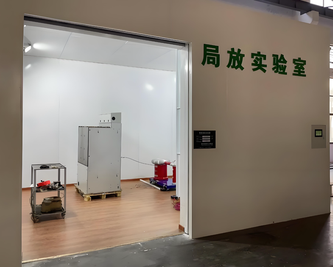
Why a shielded enclosure is required for partial discharge testing of ring main units

The reason why partial discharge (PD) testing of ring-main units (RMUs) must be carried out inside a shielded room (Faraday cage) is that PD signals are extremely weak (pico-coulomb level, pC), while the on-site electromagnetic environment is complex and the background interference is much higher than the real signal. Without shielding, the test data will be completely “drowned” in noise, making it impossible to identify defects, let alone perform quantitative evaluation. The details can be understood from the following three aspects:
I. Interference sources that the shielded room must “block”
| Interference source | Typical amplitude | Coupling path | Influence on PD testing |
|---|---|---|---|
| Spatial electromagnetic waves | Several mV–tens of mV/m | Radiation | Directly superimposed on sensor circuit, raising baseline |
| Power-conducted disturbances | Tens of mV–several V | Power lines | Enter HV circuit via coupling capacitance, create “false discharge” |
| Inverter motors, cranes, welders in workshop | Wide-band pulses | Radiation + conduction | Pulse characteristics similar to PD, extremely high false-call rate |
| Lighting, electronic ballasts of air-conditioners | Harmonics 10 kHz–1 MHz | Radiation | Can raise background by 4–6 pC, exceeding pass threshold |
In an open environment the above interferences easily lift the background to >10 pC, whereas the factory test limit for RMUs is usually ≤5 pC (new unit) or ≤10 pC (in-service unit); the signal is totally submerged and the test becomes meaningless.
II. How the shielded room achieves “low background”
The shielded room is a six-sided continuously welded metal Faraday cage. Combined with filtering and isolation, it can attenuate external interference by 60–120 dB (million–billion times), keeping the indoor background noise <1 pC so that the real PD signal can “surface”. Key technical measures are as follows:
- Electromagnetic shielding
1 mm galvanized steel plates continuously welded on all six sides; doors/windows use knife-edge + beryllium-copper finger strips; shielding effectiveness ≥80 dB at 10 kHz–1 GHz.
- Power isolation & filtering
Mains first pass through a double-shielded isolation transformer and low-pass filter, giving ≥120 dB attenuation for 10 kHz–1 MHz disturbances; indoor lighting and air-conditioner are fed separately to prevent “self-pollution”. - Fully shielded signal cables
All low-voltage signal leads use double-shielded RF coax (triax); connectors are 360° crimped, outer sheath single-point bonded to the cage to break ground loops. - No PD-generating components inside
Lamps are incandescent or DC-powered LEDs; electronic ballasts are forbidden; HV leads are polished and rounded, grading covers and epoxy supports are pre-screened to ensure no “background discharge” from any metal part. - Insulated floor
An 8 mm PPO insulating plate is placed between the shielded-room floor and the building floor, insulation resistance ≥1000 MΩ, blocking common-mode interference coupled through the station earth grid.
III. Consequences of no shielding – data become unreliable
| Test scene | Measured background | Possible outcome |
|---|---|---|
| Open workshop | 20–200 pC | Qualified units judged “over-limit”, massive false scrap |
| Ordinary switchgear room | 10–50 pC | Unable to distinguish “internal defect” from “ambient interference” |
| Inside shielded room | <1 pC | Real PD of 2–3 pC can be detected, location error ≤10 cm |
Therefore, the shielded room is not “icing on the cake” but a “hard requirement” for RMU PD testing—without it the stringent requirement of GB/T 7354 and DL/T 417 that “background noise shall be <50 % of the permissible discharge magnitude” cannot be met.
Conclusion
An RMU PD test needs a shielded room because:
- PD signals are weak (pC level) while industrial interference is strong (mV–V level), a difference of >10⁶ times;
- The shielded room reduces the background to <1 pC by “metal cage + power filter + signal shield + single-point earthing”, allowing the real defect signal to “surface”;
- Only in such a low-noise environment can quantitative measurement and accurate location be performed in accordance with the standards, avoiding false calls and missed calls, and ensuring the traceability and validity of test data.
