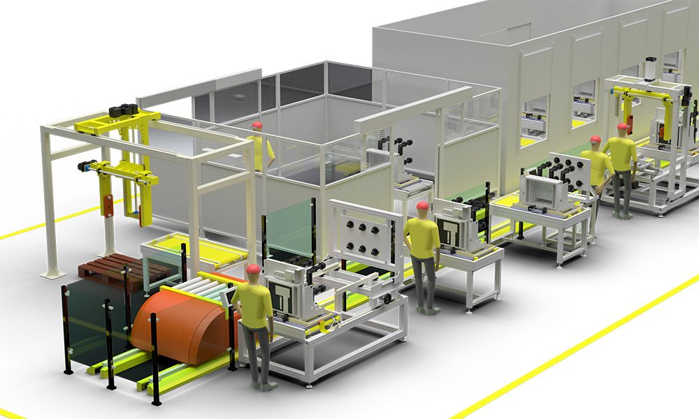
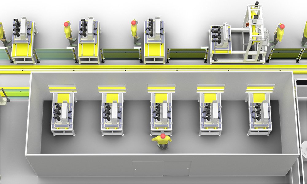
VCB Assembly Production line Layout
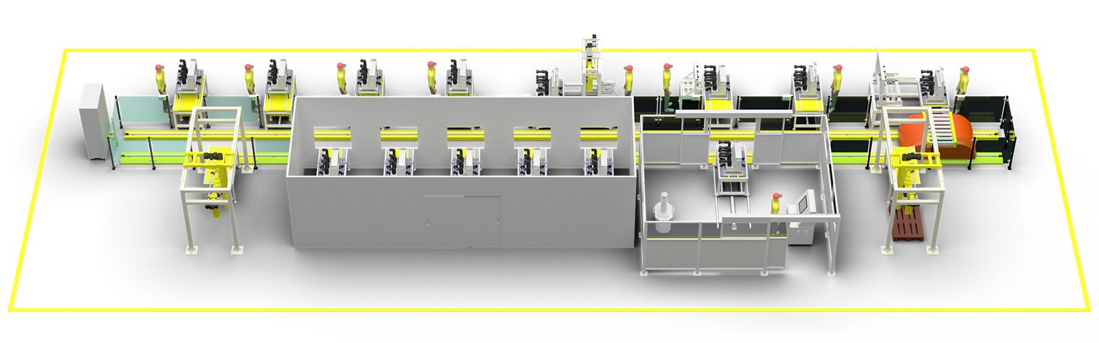
The design of the layout diagram for the production line of vacuum circuit breakers meets the assembly, production, and testing requirements of indoor vacuum circuit breakers, and is suitable for mass standardized production of VCB products.
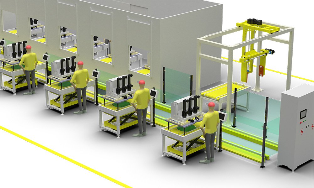
The assembly of a vacuum circuit breaker production line mainly includes the following components:
1.Housing Unit: This is the foundation of the vacuum circuit breaker, supporting all other components.
2.Enclosure: Serves to protect the vacuum circuit breaker and facilitates installation.
3.Aviation Plug: Exports the internal secondary wiring of the vacuum circuit breaker, enabling the connection between internal and external circuits.
4.Rear Cover: Provides dust protection and is equipped with control buttons for easy operation of the vacuum circuit breaker.
5.Chassis Cart: When the circuit breaker is used in cabinet installations, a chassis cart structure is adopted for easy movement and maintenance of the circuit breaker.
6.Closing Unit: Responsible for the closing action, containing multiple components that work efficiently together.
7.Tripping Unit: Responsible for the tripping action, with the opposite function to the closing unit.
8.Main Shaft Unit: Part of the operating mechanism, used to operate the vacuum arc chamber.
9.Operating Mechanism: Includes energy storage devices and transmission mechanisms, used to achieve the closing and tripping of the circuit breaker.
10.Vacuum Arc Chamber: The core component of the vacuum circuit breaker, responsible for arc extinguishing and insulation.
The testing items for vacuum circuit breakers typically include the following aspects:
1.Measurement of Insulation Resistance: This is to ensure that the insulation performance of the vacuum circuit breaker meets the requirements, usually measured with a megger.
2.Measurement of Resistance for Each Conductive Loop: Measured using the DC drop method to ensure that the resistance value of the conductive loop is within the specified technical conditions.
3.AC Withstand Test: Conducted in both the closed and open states of the circuit breaker to verify its insulation strength at the specified voltage.
4.Measurement of the Breaker Contact’s Opening and Closing Times: Including the simultaneity of opening and closing and the bounce time of the contacts after contact during closing, these parameters are crucial for the operational performance of the circuit breaker.
5.Measurement of Insulation Resistance and DC Resistance for Opening and Closing Coils and Contactor Coils: Ensuring the insulation performance and resistance values of the coils meet the factory standards.
6.Test of the Operating Mechanism of the Circuit Breaker: Verifying the functionality and performance of the operating mechanism to ensure its reliability.
7.Detection of Vacuum Degree: The core component of the vacuum circuit breaker is the vacuum arc chamber, so the detection of vacuum degree is essential.
8.Impact Test: Simulating the opening/closing actions of the circuit breaker during power faults to verify its performance under extreme conditions.
9.Visual Inspection: Checking the external quality of the vacuum circuit breaker, such as whether the paint is chipping and whether the appearance is aesthetically pleasing.